Directions Map
ConceptDraw DIAGRAM is a powerful diagramming and vector drawing software. Extended with Directional Maps Solution from the Maps Area of ConceptDraw Solution Park, it became the best software for quick and easy designing Directions Map of any complexity.

Example 1. Directions Map
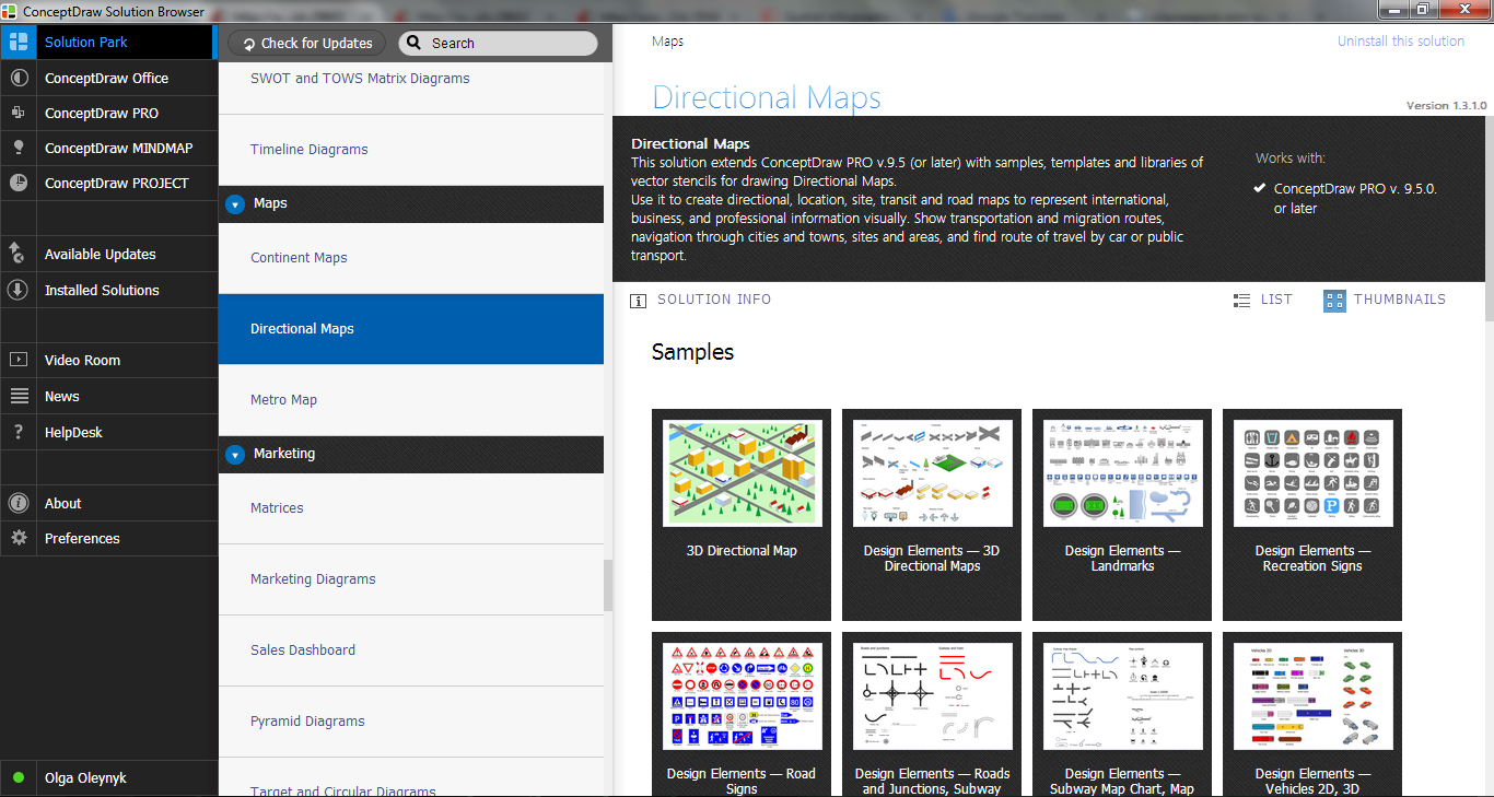
Directional Maps Solution provides the extensive drawing tools, collection of predesigned samples and templates, and 10 libraries with variety of ready-to-use vector objects:
- 3D Directional Maps
- Landmarks
- Map Symbols
- Recreation Signs
- Road Signs
- Roads and Junctions
- Subway Map Chart
- Subway and Train
- Vehicles (2D)
- Vehicles (3D)

Example 2. Directional Maps Solution in ConceptDraw STORE
338 objects offered by 10 libraries of Directional Maps Solution include all that you may need for drawing your own Directions Map. These objects can be used when you design your map at the new document, and also when you fill ready Directional Map template offered in ConceptDraw STORE.

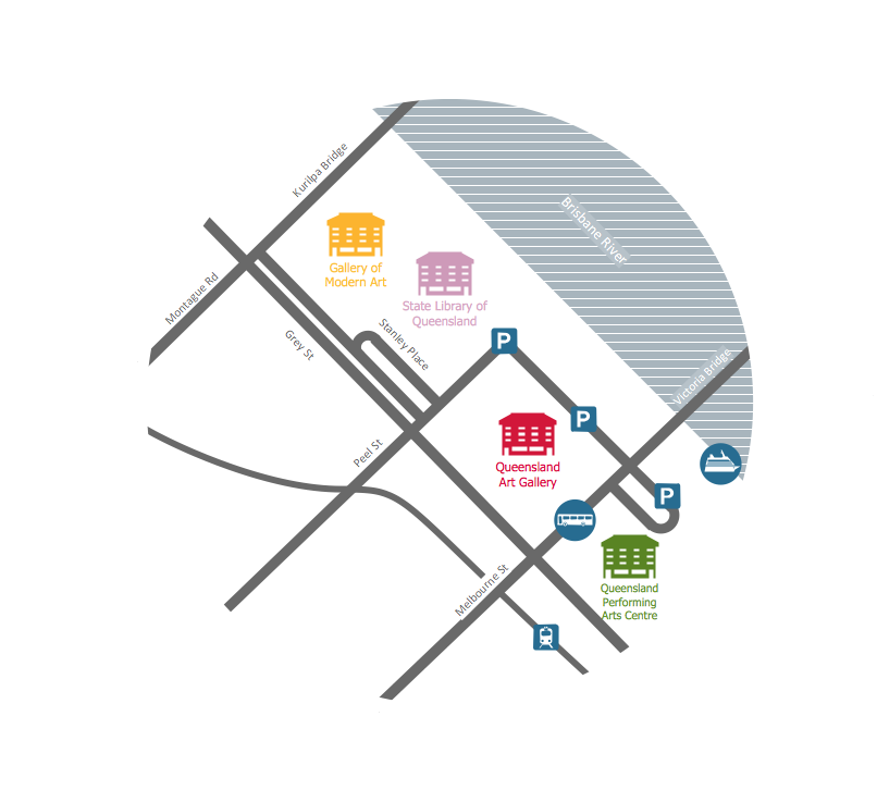
Example 3. Directions Map - Travelling to the Gallery
The samples you see on this page were created in ConceptDraw DIAGRAM software using the Directional Maps Solution for ConceptDraw DIAGRAM Solution Park. An experienced user spent 10 minutes creating every of these samples.
Use the Directional Maps Solution for ConceptDraw DIAGRAM software to create your own professional looking directions maps of any complexity quick, easy and effective.
All source documents are vector graphic documents. They are available for reviewing, modifying, or converting to a variety of formats (PDF file, MS PowerPoint, MS Visio, and many other graphic formats) from the ConceptDraw STORE. The Directional Maps Solution is available for all ConceptDraw DIAGRAM or later users.
FOUR RELATED HOW TO's:
While creating flowcharts and process flow diagrams, you should use special objects to define different statements, so anyone aware of flowcharts can get your scheme right. There is a short and an extended list of basic flowchart symbols and their meaning. Basic flowchart symbols include terminator objects, rectangles for describing steps of a process, diamonds representing appearing conditions and questions and parallelograms to show incoming data.
This diagram gives a general review of the standard symbols that are used when creating flowcharts and process flow diagrams. The practice of using a set of standard flowchart symbols was admitted in order to make flowcharts and other process flow diagrams created by any person properly understandable by other people. The flowchart symbols depict different kinds of actions and phases in a process. The sequence of the actions, and the relationships between them are shown by special lines and arrows. There are a large number of flowchart symbols. Which of them can be used in the particular diagram depends on its type. For instance, some symbols used in data flow diagrams usually are not used in the process flowcharts. Business process system use exactly these flowchart symbols.
Picture: Basic of Flowchart: Meaning and Symbols
Related Solution:
Plumbing systems are very important for any manufacture, and it's a good practice to have a clear scheme of that system. To create one, you should use a piping and instrumentation diagram software with a possibility to save files in vector format, so you can print them without quality loss. ConceptDraw DIAGRAM is a great tool for creating diagrams, and you don't need to be very experienced to use it efficiently.
This example of Piping and Instrumentation Diagram (P&ID) depicts a scheme that illustrates the physical sequence and functional communications of piping, instrumentation and plumbing equipment components of a typical food trailer.
Seeking to avoid health troubles in a mobile food service , the plumbing demands for food trailers must be considered accurately. This P&ID shows all of piping including a basic set of piping system components along with multiple sinks, extra water heaters and other elements to meet health guidelines.
Picture: Piping and Instrumentation Diagram Software
Related Solution:
Samples, templates and libraries contain vector clip art for drawing the Road Transport Illustrations.
Picture: Road Transport - Design Elements
Related Solution:
You are probably familiar with diagrams. But have you ever thought that they are useless? This article will explain you why.
Picture: Diagrams Mean Nothing
Related Solution:


