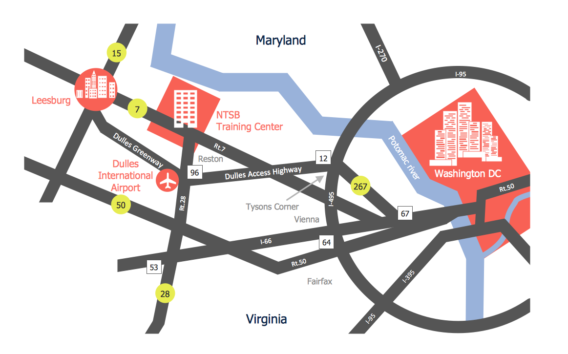
Example 1. Directions Maps - NTSB Training Center Location
Directional Maps Solution provides wide variety of Directions Maps samples and examples, and also 2D and 3D Directions Maps templates which are available for using from ConceptDraw STORE.
You are able to use any of them and also the predesigned objects from numerous libraries of Directional Maps Solution to facilitate your work for the Directions Maps drawing. Use of ready template as the base is the easiest way of drawing.

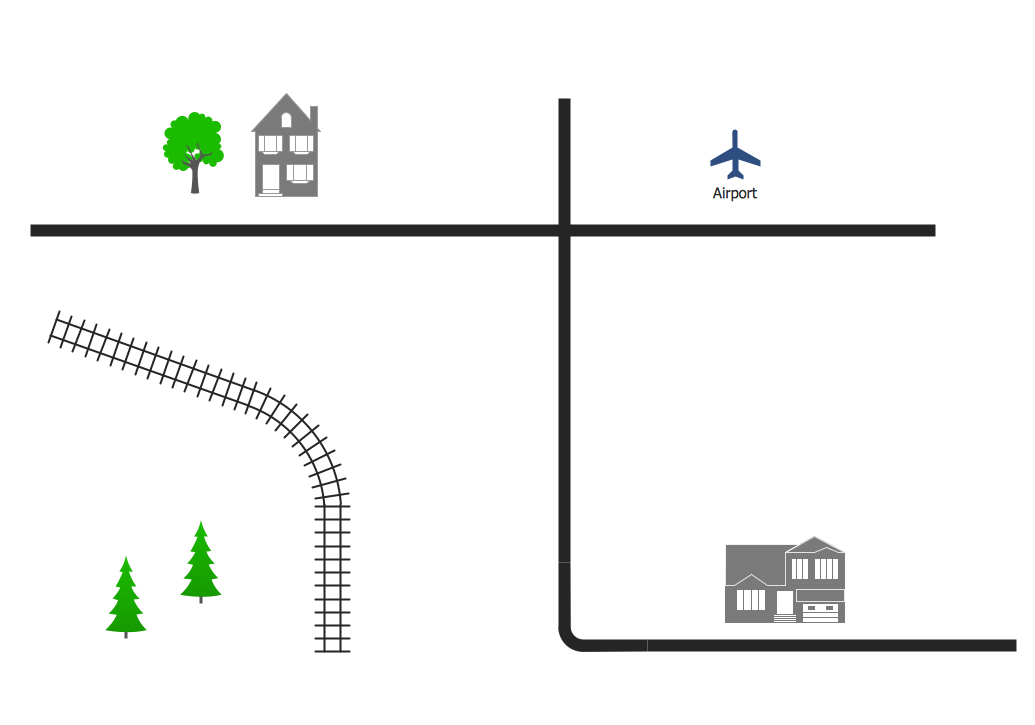
Example 2. Directions Maps - Neighborhood 3D Directional Map
The samples you see on this page were created in ConceptDraw DIAGRAM software using the predesigned shapes from the Directional Maps Solution libraries. An experienced user spent 10 minutes creating every of these samples.
Use the Directional Maps Solution for ConceptDraw DIAGRAM software to create your own professional looking directions maps of any complexity quick, easy and effective, and then successfully use them in your work and life activity.
All source documents are vector graphic documents. They are available for reviewing, modifying, or converting to a variety of formats (PDF file, MS PowerPoint, MS Visio, and many other graphic formats) from the ConceptDraw STORE. The Directional Maps Solution is available for all ConceptDraw DIAGRAM or later users.
TEN RELATED HOW TO's:
ConceptDraw DIAGRAM diagramming and vector drawing software extended with Directional Maps Solution from the Maps Area of ConceptDraw Solution Park is a powerful maps and directions design software. Let's review the tools of this solution.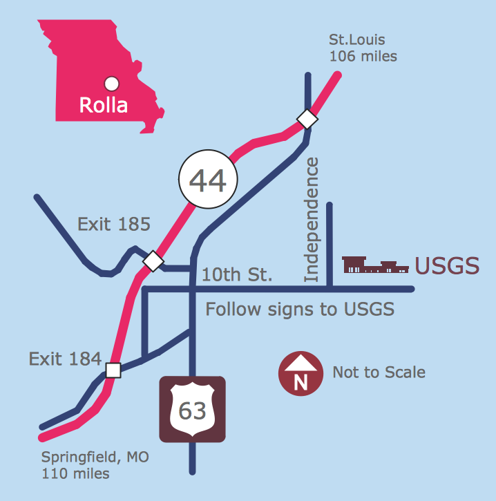
Picture: Maps and Directions
Related Solution:
Drawing an electric circuit plan with all the wiring might seem very complex. If you ever felt afraid to ask how to use electrical and telecom plan software, then it’s time to actually start from altering the templates from the Solution Park. You won’t even notice the moment when you would become an experienced user.
This electrical and telecommunication floor plan plan presents electrical and telecommunication devices located in a country house floor plan. Each electrical or telecom device on this plan is indicated with the particular symbol. Using standard Electrical and Telecommunication symbols makes this floor plan clear for anybody who will be involved into construction process. All the electrical and telecom symbols used in the current floor plan are placed to a legend. This electrical and telecom floor plan can be included as a separate piece into a package of building documentation.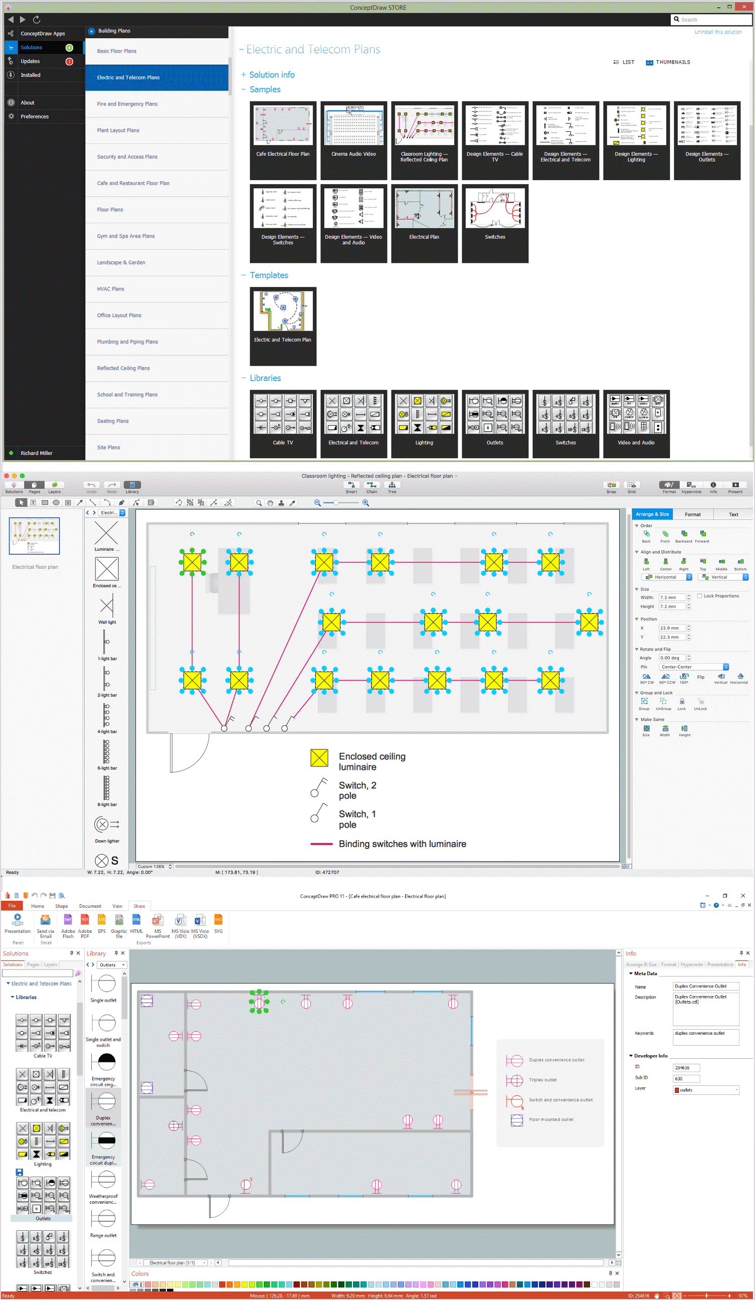
Picture: How To use Electrical and Telecom Plan Software
Related Solution:
Aside from decorating inner spaces, which is a realm of interior design, the art of exterior design is about home facades, playgrounds and yards. To start a project, first of all, you need a site plan of the place, and a list of customers’ requirements. With special software you can do a plan of any place like parking, interchange or driveway easily.
There is one of the three libraries supplied with ConceptDraw Site Plans solution. It is designed to draw planning areas adjacent to buildings. For example parking, exit road or house territory for rest. This kind of building plans can be used for providing parking control that helps to organize traffic near residential areas. The well considered road planning will improve safety and will help to manage the number of vehicles near buildings. The ConceptDraw library "Parking and Roads" includes vector graphic images of parking spaces, lots and strips as well as street junctions, driveways and interchanges.
Picture: Interior Design. Site Plan — Design Elements
Related Solution:
This diagram represents the electrical floor plan. This is a common practice - to draw the electrical plan on the floor plan. The outlets, fixtures and other electrical equipment are depicted on the floor plan with special symbols. This drawing was created using the possibilities of ConceptDraw DIAGRAM as CAD software. Computer-aided design software is intended to replaces manual engineering drafting with an automated process. CAD software is used by engineers, architects, and others to make high-precision technical drawings and illustrations. CAD software allows technical specialists to develop, examine and manage various engineering projects.
It is almost impossible nowadays to imagine mechanical engineering without digital technologies. Finding a suitable CAD software for creating mechanic diagram and electrical diagram architectural designs can take a lot of time and effort. However, with ConceptDraw DIAGRAM you can create any diagram that you want and later convert it to the most popular graphic formats like.vsdx,.png,.pptx etc.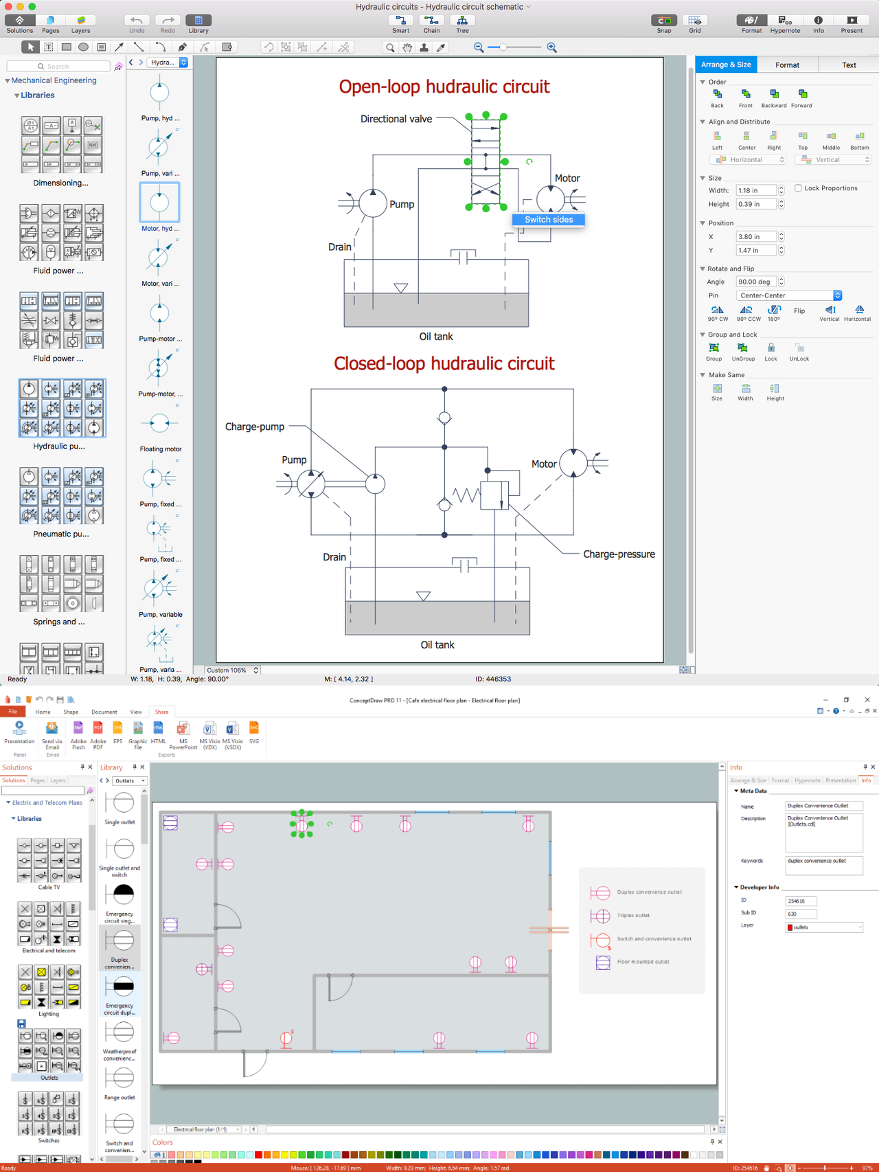
Picture: CAD Drawing Software for Making Mechanic Diagram and Electrical Diagram Architectural Designs
Related Solution:
There are numerous articles about the advantages of flowcharting, creating business graphics and developing different charts. Nevertheless, these articles are almost useless without the main component - the examples of flowcharts, org charts and without a fine example, it is difficult to get all the conveniences of creating diagrams. You can find tons of templates and vivid examples on Solution Park.
This illustration shows a variety of business diagrams that can be created using ConceptDraw DIAGRAM. It comprises a different fields of business activities: management, marketing, networking, software and database development along with design of infographics and business illustrations. ConceptDraw DIAGRAM provides a huge set of sample drawings including business process modeling diagrams,, network diagrams, UML diagrams, orgcharts, DFD, flowcharts, ERD, geographical maps and more.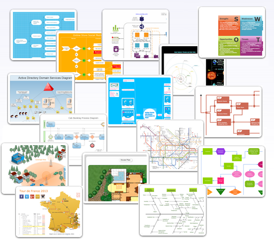
Picture: Examples of Flowcharts, Org Charts and More
Related Solution:
Value Stream Map template helps you to create VSM diagrams using ConceptDraw DIAGRAM software.
Picture: How To create Value Stream Map (VSM)
Related Solution:
ConceptDraw DIAGRAM software extended with Directional Maps Solution from the Maps Area of ConceptDraw Solution Park offers you the set of useful tools for easy drawing map directions, directional maps, road maps, navigation schemes, transit maps of any complexity, etc.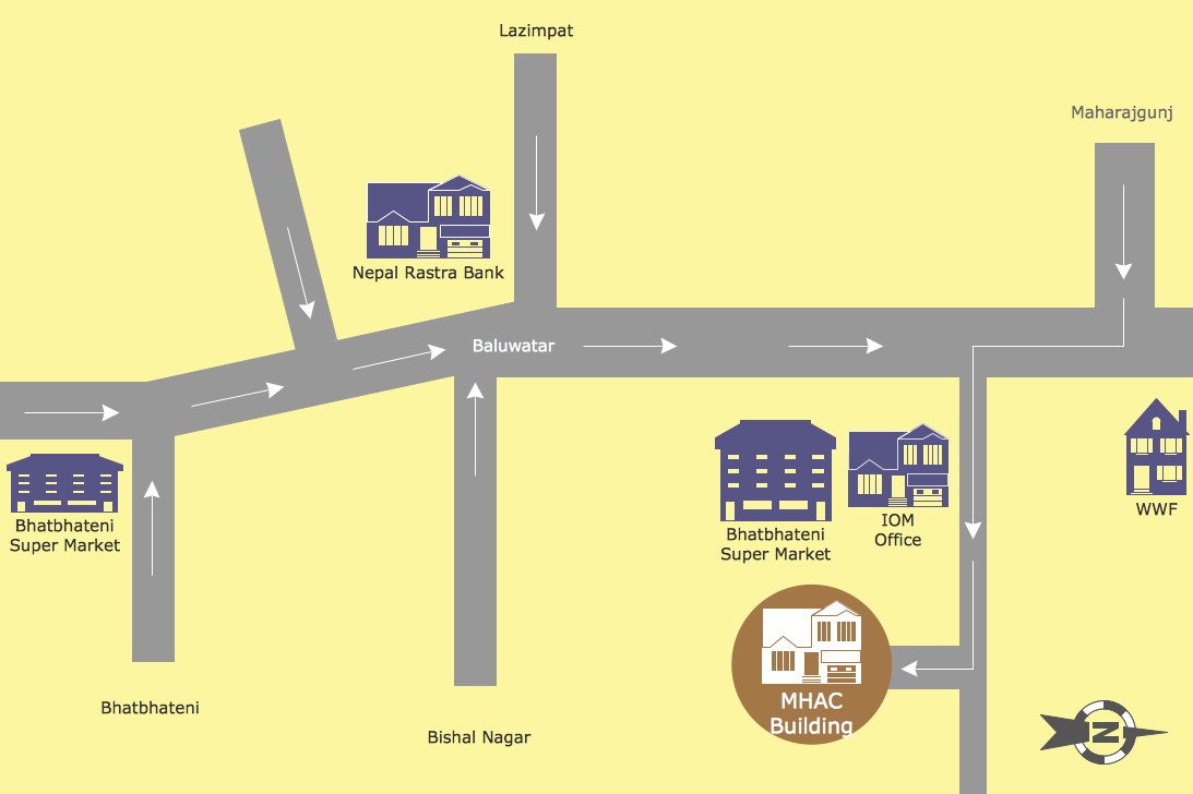
Picture: Map Directions
Related Solution:
ConceptDraw DIAGRAM is a powerful diagramming and vector drawing software. Extended with Directional Maps Solution from the Maps Area of ConceptDraw Solution Park, it became the best software for quick and easy designing Directions Map of any complexity.
Picture: Directions Map
Related Solution:
When thinking about data visualization, one of the first tools that comes to mind is a flowchart design. You can find flowchart symbols, shapes, stencils and icons easily on the Internet, but it might take time to systematize this information. Nevertheless, once you start flowcharting, you’ll love its simplicity and efficiency.
This diagram consists from standard flowchart symbols, approved by ANSI (American National Standard Institute) for drawing flowcharts. A flowchart is a diagram that represents a step-by-step algorithm of any process, displaying the process stages as boxes that are connected with arrows. Flowchart design makes it clear and readable.
Flowchart designed using ConceptDraw DIAGRAM flowchart software allows to make attractive and clear process presentation, it makes interpretation of the business process flow fresh and versatile. Great flowchart design view is a big advantage over the diagram created manually on a paper.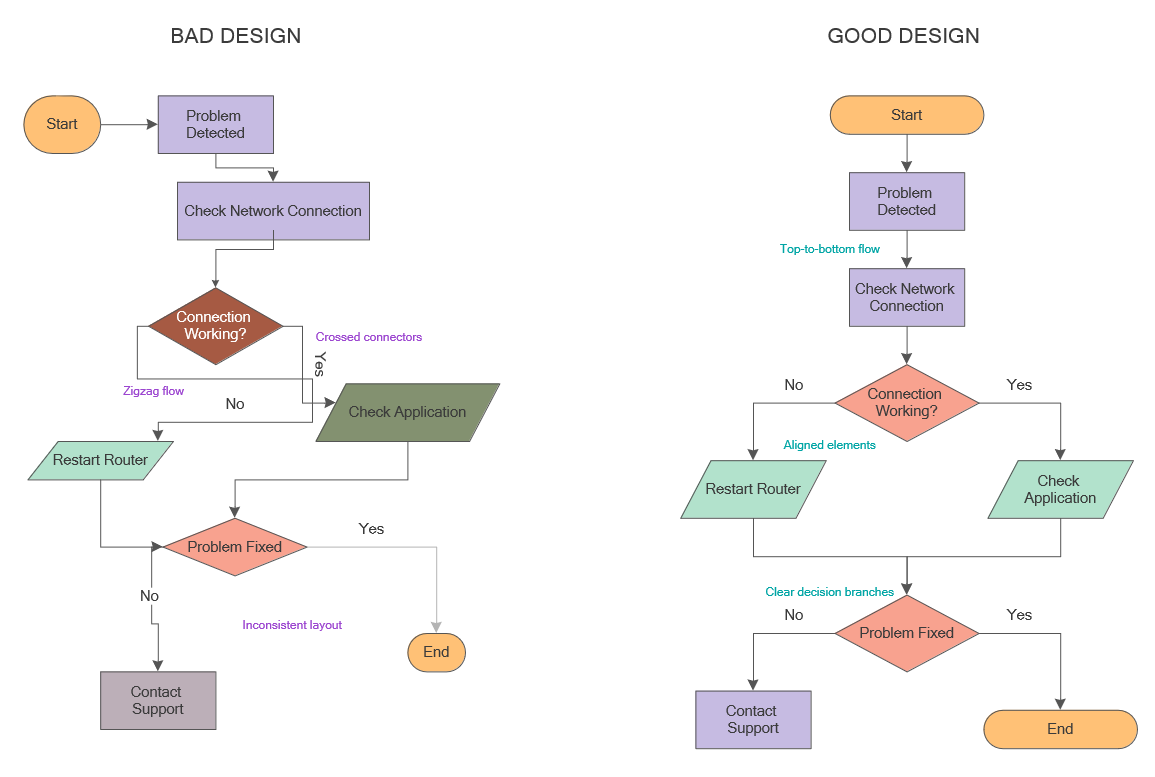
Picture: Flowchart Design: Principles, Layout, Symbols and Best Practices
Related Solution:
You need visually represent the Maps Driving Directions? Now it's incredibly easy to do this in ConceptDraw DIAGRAM diagramming and vector drawing software which was supplied with unique Directional Maps Solution from the Maps Area.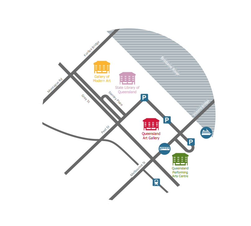
Picture: Maps Driving Directions
Related Solution: