Jacobson Use Cases Diagram
In systems engineering as well as in software engineering, a “use case” is a list of event steps or actions, typically defining the interactions between a “role” and a system in order to achieve a goal. The “actor” can be some person or any other representative of the external system. In the systems engineering, use cases are usually deployed at a higher level than within the software engineering itself, representing missions or goals, so-called “stakeholder goals”. The requirements after can be captured in the SysML or as the contractual statements. The analysis of the “use cases” in a very important technique, which is used in the software engineering since 1992. “Use case driven development” is the main characteristic of so many different process models as well as the frameworks, for example, the Unified Process (UP), ICONIX, the IBM Rational Unified Process known as RUP, as well as the method called “Oracle Unified Method” or “OUM”.
The textual, visual and structural modelling techniques were first formulated by Ivar Jacobson in 1986 for the purpose of specifying the term of the “use cases”. In 1992 Ivar Jacobson’s co-authored the book called “Object-Oriented Software Engineering - A Use Case Driven Approach” that helped him to popularize the technique for capturing the so-called “functional requirements”, partially used in the software engineering development. Since then, other experts have also contributed their additions to the technique. Among them there were Larry Constantine, Alistar Cockburn, Dean Leffingwell, Gunnar Overgaard and Kurt Bittner.
In 2011, Jacobson published an update to his work and he called it “Use Case 2.0”. His intention was to incorporate different practical experiences of him in applying use cases since the original inception of the concept. Jacobson’s partner Cockburn describes a better, more detailed structure, for a use case, although he permits it to be more simplified in case there are fewer details, which might be needed to mention. His use case template can be applied in the fields, such as “Primary Actor”, “Title: "an active-verb goal phrase that names the goal of the primary actor", “Goal in Context”, “Scope”, “Level”, “Stakeholders and Interests”, “Precondition”, “Minimal Guarantees”, “Success Guarantees”, “Trigger”, “Main Success Scenario”, “Extensions” and “Technology and Data Variations List”.
Cockburn also suggested using two devices for the nature of each use case indication, such as icons for goal level and design scope. Cockburn approach has also influenced the other authors, such as Beus-Dukic, who develops the so called “fully dressed use case” template. But their fields were different from Cockburn and they were “Variation scenarios”, “Exceptions” (for example, the exception events as well as their exception-handling scenarios), etc. They insisted on the use cases being not only texts but also diagrams, in case it is needed. The relationships between use cases and actors in the Unified Modelling Language are represented in a way of the use case diagrams, which are originally based upon Ivar Jacobson’s so-called “Objectory notation”.
In order to visualize use cases, the other UML diagrams can be used. Among them there are “sequence diagrams”, “communication diagrams”, “state machine diagrams” and “activity diagrams”. In general, a so-called “System Sequence Diagram” or “SSD” is the one being used in order to show the interactions between the system under design (SuD) and the external actors. The most common reason for showing that is visualizing a particular scenario of a use case or use cases.
Conducting the use case analysis means drawing the use case diagrams as the first step of this process. For simple and small project use a model of a few UML diagrams can be used. Such diagrams may depict the use cases as well as a few textual descriptions. The visual diagram representations of use cases are also very effective in terms of facilitating the better understanding, design of some complex system and communication.
There are many benefits of using the use cases as they, first of all, constitute a user-centric tool for the software requirements specification processes. Their modelling usually starts from identifying the key stakeholder roles or actors, interacting with the system. The goals and objectives, which the system must fulfill, have to be clarified at the very first stage. Such goals and objectives become the ideal candidates for the titles of the use cases afterwards, representing the desired functional features provided by the system.
Use cases are often written in natural languages with the structured templates as this narrative textual form foster better communications among all stakeholders (including end-users, customers, developers, managers as well as testers). The better way of communication results in quality requirements and thus these quality systems are delivered. Another powerful thing about use cases resides in the formats of the use case samples, the main success scenario known as “basic flow” and the extension scenario fragments in particular. Analyzing any use case step by step, as well as investigating and exploring every action step of the use case flows from its very basic form to the different extensions, for identifying those tricky and often costly requirements, is one of the structured and beneficial ways to get clear, as well as stable and quality requirements on a systematic basis.
Using ConceptDraw DIAGRAM software for making the previously described in detail use case diagrams is one of the best options available nowadays. The reason of this software being so popular today is that it allows having the examples of already previously created diagrams which all can be used while creating your own ones. For example, if you have no idea of where to start from and what to do in order to make a great looking use case diagram, then you can simply find the template of it in one of the solutions, available for all of the ConceptDraw DIAGRAM users. In this case the “Rapid UML solution” from “Software Development area” of “ConceptDraw Solution Park” from this site can match your needs in the best way. Having it means, apart from having the samples of all pre-made diagrams, getting the vector stencils library “UML Use Case”, which contains the specific design symbols of the UML notation (such as actors, actions, associations and relationships) in order to use while working in the ConceptDraw DIAGRAM diagramming and vector drawing software.
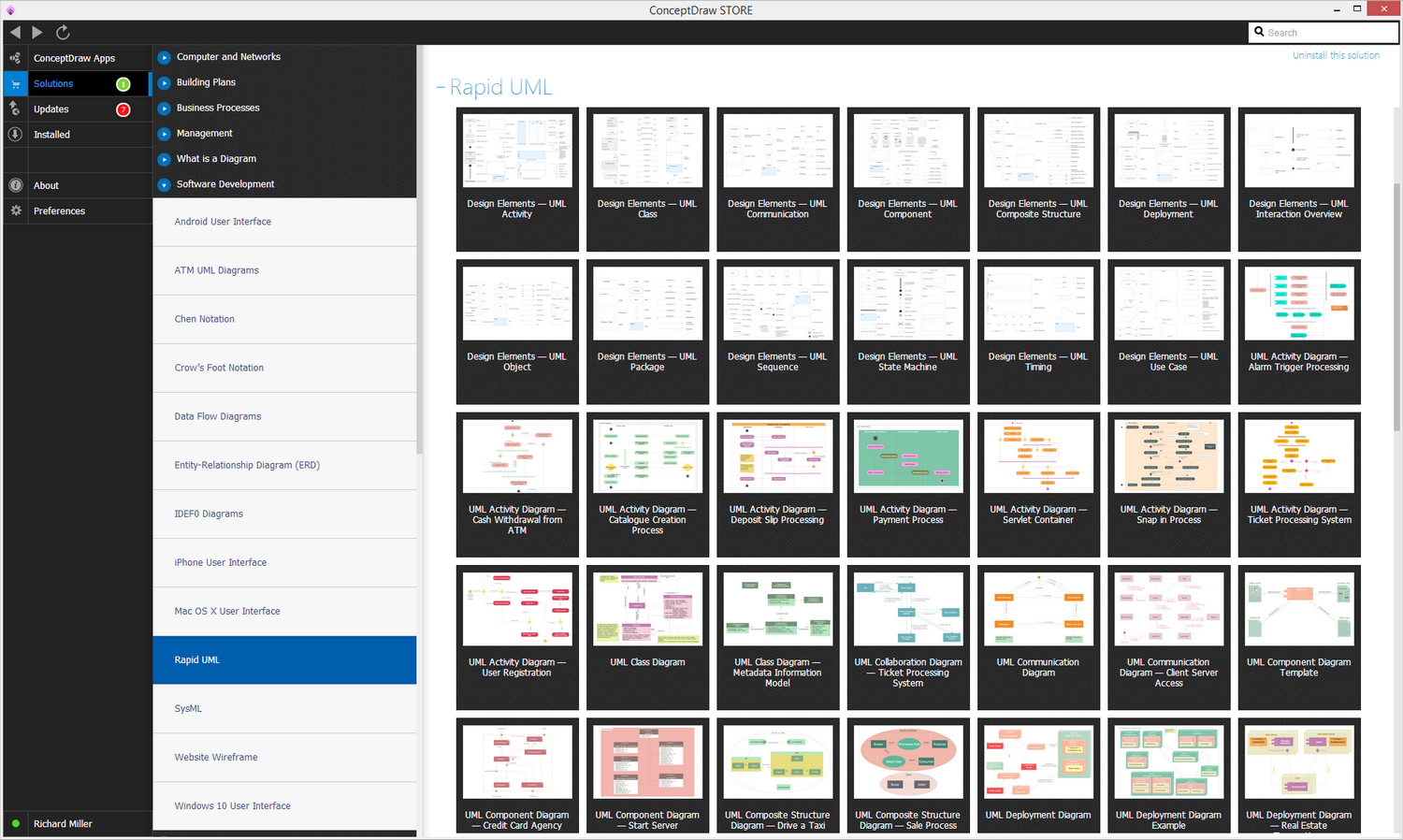
Example 1. UML Solution in ConceptDraw STORE
Use the UML Use Case library to draw use case models for your business documents, presentations and websites.

Example 2. Jacobson Use Cases Diagram — Restaurant System
The example above shows an use case model of a restaurant business.
Software Diagram Resource:
- Software Diagrams
- SSADMN Diagram
- Yourdon and Coad Diagram
- Command OLE Diagram
- Block Diagrams
- Data Modeling Diagram
- SysML Diagram
- Chen RED Diagram
- Martin RED Diagram
- IDEF0 Diagram
- Booch OOD Diagram
- Gane Sarson Diagram
- Memory Object Diagram
- Data Flow Diagram
- FlowCharts
- Graphic User Interface (GUI)
- UML Diagram
- Language Level Shapes Diagram
- ORM Diagram