Made with
ConceptDraw
DIAGRAM 17

Radio networks.
Computer and Network Examples

A Radio network is a network system that distributes the radio programming on the multiple radio stations. There are two types of radio networks: one-to-many broadcast network and two-way radio type.

The one-to-many broadcast network is usually used for the mass media entertainment, public information.

The two-way radio type networks are used for the public services and public safety. They are usually set up with fixed broadcast points with co-located mobile receivers/transmitters or transceivers.

ConceptDraw DIAGRAM is a powerful network diagramming and vector drawing software. It provides the Computer and Networks Area with many Solutions that contain the wide set of ready-to-use predesigned vector stencils and examples to help you design the professional looking Radio networks of any complexity quick and easy.

Radio networks. <br>Computer and Network Examples *

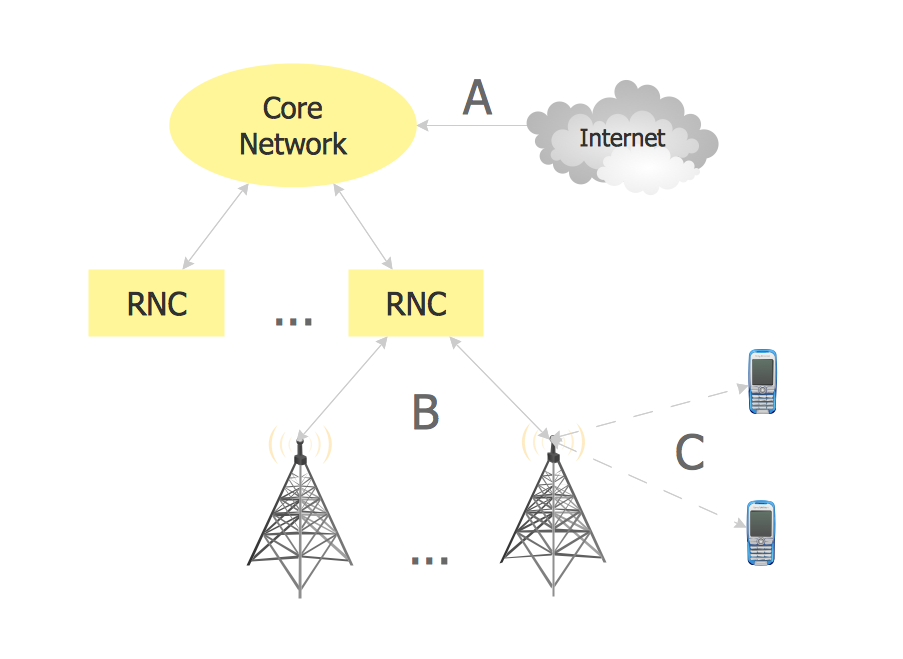
Example 1. Radio network.

This example was created in ConceptDraw DIAGRAM using the Computer and Networks Area of ConceptDraw Solution Park and shows the Radio network.

The network diagrams designed with ConceptDraw DIAGRAM are vector graphic documents and are available for reviewing, modifying, and converting to a variety of formats (image, HTML, PDF file, MS PowerPoint Presentation, Adobe Flash or MS Visio).


See also Samples:


THREE RELATED HOW TO's:
A transformer is an electrical device that transfers electrical energy between two or more circuits through electromagnetic induction. Electromagnetic induction produces an electromotive force within a conductor which is exposed to time varying magnetic fields. Transformers are used to increase or decrease the alternating voltages in electric power applications. 26 libraries of the Electrical Engineering Solution of ConceptDraw DIAGRAM make your electrical diagramming simple, efficient, and effective. You can simply and quickly drop the ready-to-use objects from libraries into your document to create the electrical diagram.Electrical Symbols — Transformers and Windings *
Picture: Electrical Symbols — Transformers and Windings
Related Solution:
The reliability is a cornerstone for any corporate computer network. If you want to provide a high fault tolerance, a mesh network topology would be the solution. The main advantage of this network is that every node can work as a commutator, although it’s not easy to set up this kind of network. A mesh network topology may be full, or partial. Full mesh network means that each node of the network (computer, workstation or other equipment) is connected directly to each of the other nodes. A partial mesh topology means that a part of nodes are connected with a whole network, and the other part of nodes are only connected to those equipment, they exchange the majority of data. This illustration shows schematic diagram of a partial mesh network containing six nodes. Each node is represented as a circles and connections are drawn as straight lines. The connections may be both wired and wireless. This scheme can be used to make the specific logical or physical network diagrams by means the ConceptDraw Computer and Networks solution.Mesh Network Topology Diagram *
Picture: Mesh Network Topology Diagram
Related Solution:
ConceptDraw DIAGRAM is a Wireless Network Drawing Mac OS software.Wireless Networking for Mac *
Picture: Wireless Networking for Mac
Related Solution:
ConceptDraw
DIAGRAM 17