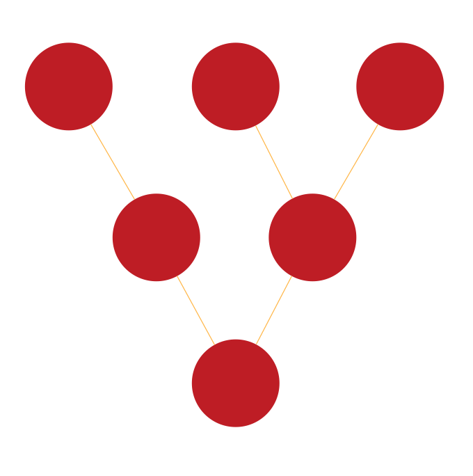
Tree Network Topology Diagram
Tree Network Topology Diagram
Computer network diagrams, including all of the network topology diagrams, can be created with the help of ConceptDraw DIAGRAM software and they all can be made only within a couple of hours or even minutes using our solutions. There are eight basic topologies, which are: “Point-to-point”, “Bus”, “Star”, “Ring or circular”, “Mesh”, “Tree”, “Hybrid” and “Daisy chain”. So you can always make Point-to-point network topology diagram, Bus network topology diagram, Star network topology diagram, Ring network topology diagram, Mesh network topology diagram, Tree network topology diagram, Hybrid network topology diagram and Daisy chain network topology diagram. With ConceptDraw DIAGRAM application you will find it much simpler to create any of those, mentioned above diagrams.
“Bus” topology includes the possibility of making the “Linear bus” topology and the “Distributed bus” topology diagrams. The “Point-to-point” topology diagram can be made using a dedicated link between its two endpoints. “Mesh” network diagram describes the network, where the nodes relay data for the network itself. All of the nodes in this “mesh” topology diagram cooperate with each other in the process of the data distribution within the network. “Mesh” network topology can be used for both wireless and wired networks. The “ring” topology is quite similar to the “bus” one. In this topology data travels around the ring, but in only one direction. When one of the nodes sends data to another node, then this data passes through each of the intermediate nodes on the ring until it reaches the planned destination. Then, the intermediate nodes transmit this data to keep the signal strong and so each of the nodes is a peer, and there is no hierarchical relationship of clients in the “ring” topology. “Hybrid” network topologies are those, which combine a few different types of topologies. For instance, it can be the “ring” topology and the “mesh” topology, it can be also a “mesh” one and “bus” one, “star” network topology combined with the “mesh” one, etc.
A “tree” network, if it is connected to another “tree” network, will still be a “tree” one. This type of network topologies has a hierarchy of nodes and its highest level has a single (also known as a “root”) node, which is connected with another single or multiple node or nodes. There is the lower level nodes in “tree” computer network topology, which is also connected to a single node or multiple nodes in the next level under the previous, the higher one. “Tree” computer networks have not so many levels, but each of the nodes in this “tree” network has definite nodes, which are connected to it at the next, which is a lower, level in this network topology hierarchy. Shortly to say, the “tree” computer network topology is a combination of both “Star” and “Bus” computer network topologies.
A “hybrid” network topology can be used for illustrating the two different basic network topologies, which are connected to each other. There is another topology called “fully connected computer network topology”. It can be also known as a “full mesh computer network topology” and it is one of the existing computer network topologies, where there is a direct link between all pairs of the nodes within this topology. In this “fully connected computer network topology” with “n”-nodes there are n(n-1)/2 direct links. The computer networks, which are designed with this type of the computer network topology called “a full mesh computer network topology”, are usually very expensive to have. Although they provide a good reliability as there are many paths for data and all of them are provided by the many redundant links, which are all between the nodes. This “fully connected computer network topology” or, as it is also known, a “full mesh computer network topology” can be seen in many of the military applications.
In case you want to create one of the mentioned above computer network topology diagrams, then you can use ConceptDraw DIAGRAM application, as it allows to use another application for getting the solutions from for working with the first mentioned software. This another product of CS Odessa is called “ConceptDraw STORE” and downloading it can help you with your drawings as within this application you can always find any needed solution, such as “Computer and Networks” solution, which can also be found in the Computer and Networks area of ConceptDraw Solution Park on this site. This solution provides ConceptDraw DIAGRAM users with a bunch of templates and a huge variety of libraries, full of symbols of local area network (LAN) and wireless LAN (WLAN) equipment.
You can always take this chance to save your time with ConceptDraw DIAGRAM software, as it provides all those needed examples and templates of ready-to-use charts, flowcharts, schemes, plans, matrices and diagrams, including the “Tree” network topology ones, created by IT professionals of CS Odessa based in Ukraine.
Our product “ConceptDraw DIAGRAM is a very special and unique tool, which is now very popular among those who deal with drawings, including the web designers, marketing managers and other IT specialists and engineers. There is, obviously, a reason for this software to be that popular and this reason is the following: ConceptDraw DIAGRAM application allows its users to create any drawing and it usually takes only a couple of hours or even, sometimes, a couple of minutes, as having the solutions we offer simplifies our clients’ work. Having the professionally looking templates and stencils, which are design elements for making the network topology diagrams, including the “Tree” network topology diagram and others. Downloading ConceptDraw DIAGRAM software can allow you to also use ConceptDraw STORE after downloading it on this site as this another application can be very useful for you as you can find solutions, including the “Computer and Networks” one there.
The Computer and Networks solution from Computer and Networks area of ConceptDraw Solution Park provides examples, templates and vector stencils library with symbols of local area network (LAN) and wireless LAN (WLAN) equipment.
Use it to draw the physical and logical network topology diagrams for wired and wireless computer communication networks.

Pic. 1 Tree Network Topology
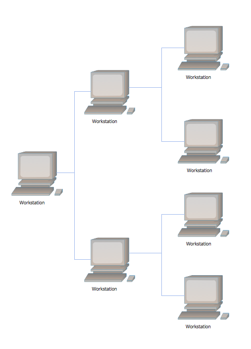
Pic. 2. Tree Network Topology Diagram
"definition: Tree topology is a combination of Bus and Star topology.
An example of this network could be cable TV technology. Other examples are in dynamic tree based wireless networks for military, mining and otherwise mobile applications. The Naval Postgraduate School, Monterey CA, demonstrated such tree based wireless networks for border security. In a pilot system, aerial cameras kept aloft by balloons relayed real time high resolution video to ground personnel via a dynamic self healing tree based network."
[Network topology. Wikipedia]
See Also Network Topologies:
TEN RELATED HOW TO's:
Visio Files and ConceptDraw. ConceptDraw DIAGRAM is compatible with MS Visio.VDX formatted files.VDX is Visio’s open XML file format, and it can be easily imported and exported by ConceptDraw DIAGRAM.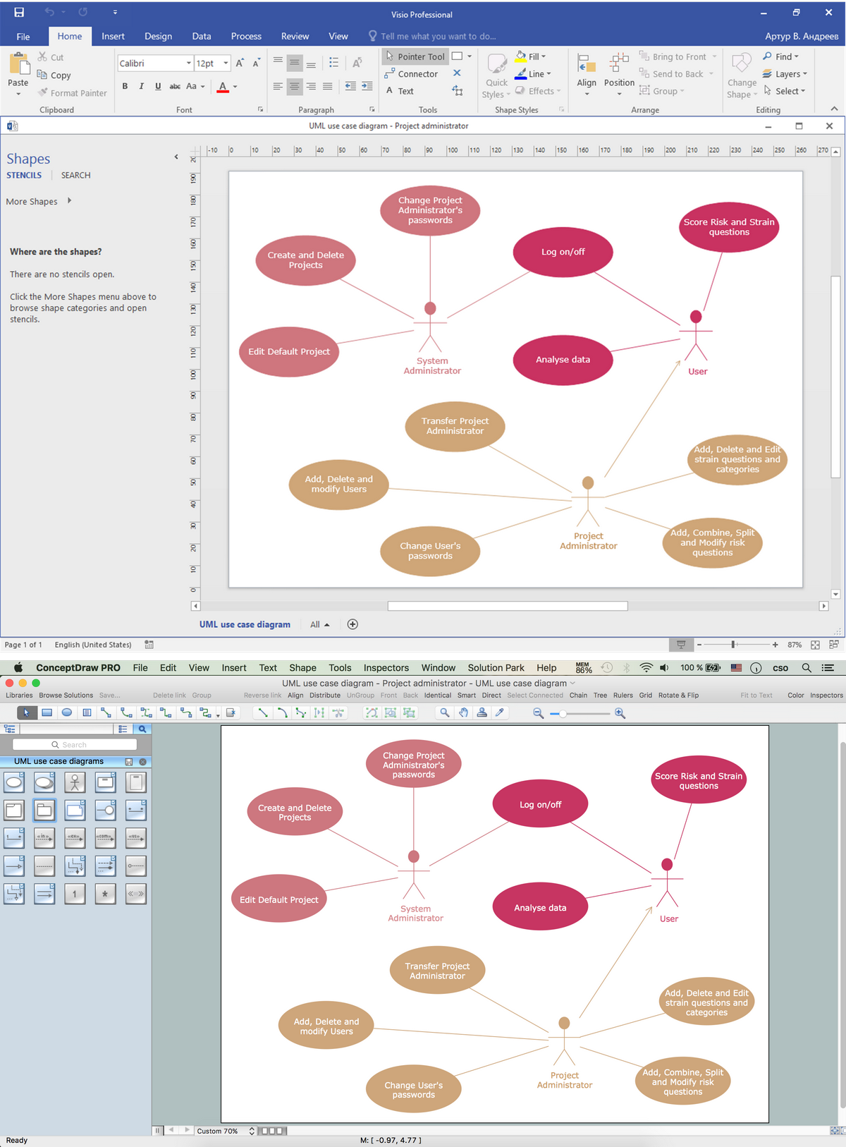
Picture: Visio Files and ConceptDraw
A cozy atmosphere is crucial for the success of any cafe or restaurant. To provide it, you should use restaurant floor plan software at the stage of design. If your establishment is located conveniently and has a harmonic atmosphere inside it, this is bound to be a success.
This sample Restaurant floor plan illustrates the possibilities of ConceptDraw solution for Cafe and Restaurant plans. It represents the location of the restaurant's main hall with its furnishing as well as a plan of kitchen and toilets. Generally, Cafe and Restaurant Plans solution has a big set vector images of tables, seats, lightening, etc. Using them you will be able to plan the restaurant of your desire with an incredible design and spirit.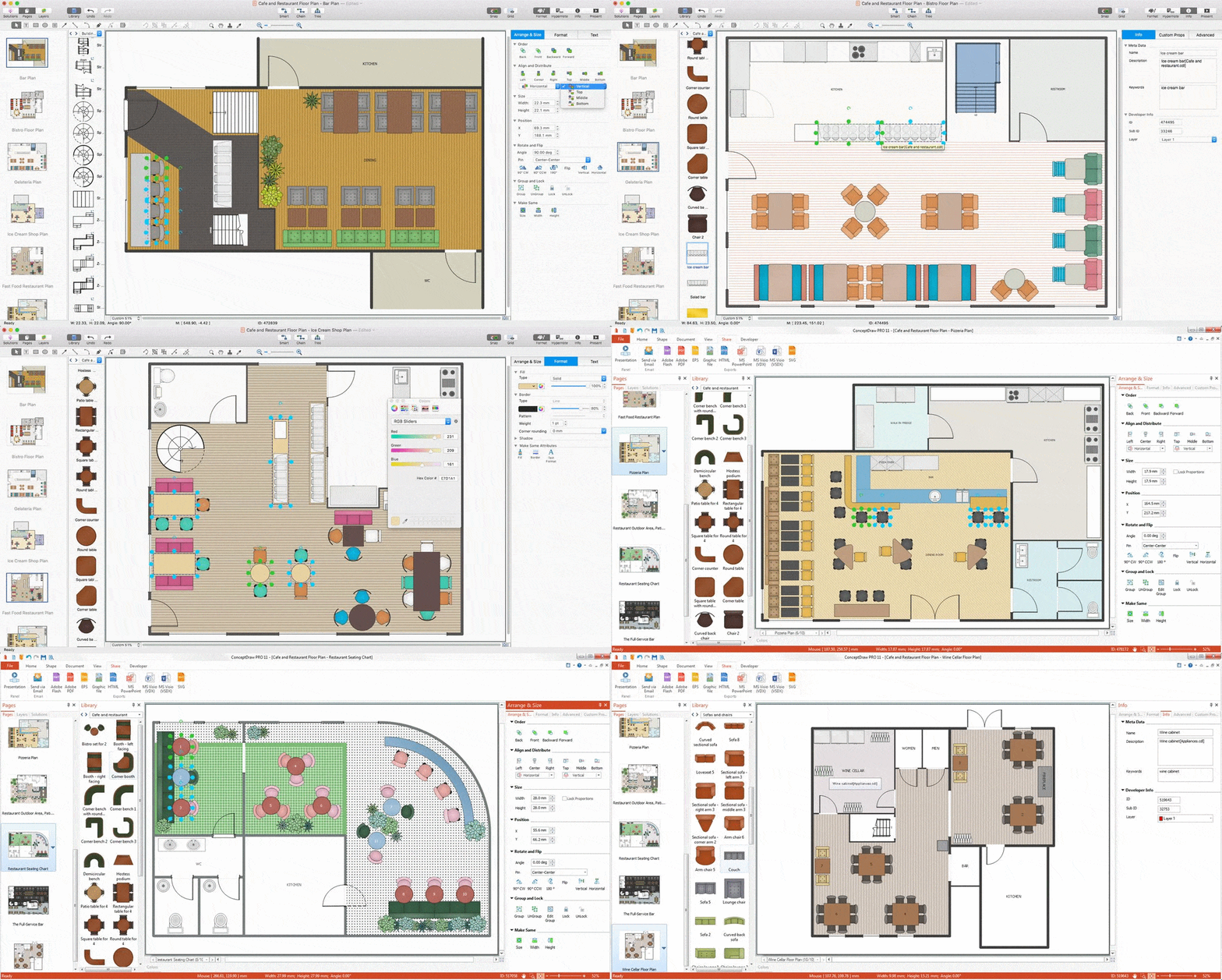
Picture: Restaurant Floor Plan Software
Related Solution:
ConceptDraw DIAGRAM is the best network diagram software. To design the Cisco Network Diagrams and visualize the computer networks topology use ConceptDraw DIAGRAM diagramming and vector drawing software extended with Cisco Network Diagrams solution for ConceptDraw DIAGRAM Solution Park.
Picture: Cisco Network Diagram Software
Related Solution:
Drawing the network diagrams is a complex process which requires a lot of efforts, time and artistic abilities. ConceptDraw DIAGRAM offers the Network Layout Floor Plans Solution from the Computer and Networks Area with variety of predesigned network components for drawing network layout floor plans in minutes.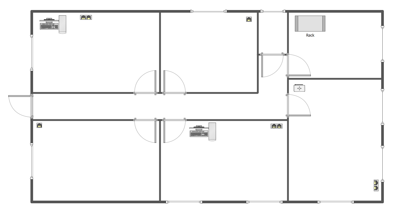
Picture: Network Components
Related Solution:
A network diagram represents the set of computers and network devices and the connections among them. This scheme can be developed for any institution or establishment. To illustrate this concept let’s take for example, a hotel network topology diagram or a school network diagram. These diagrams depict access points, servers, workstations, firewalls and another equipment needed to provide a network.
On this masterpiece drawing one will see a simple scheme a of connecting computers together. Such form of connecting can be applied for a hotel, guest house, bungalow, hut or something else. This diagram shows the images of the real LAN components. So, it represents a physical category of a network construction. It looks similar to a star - so this network configuration is named a star topology. The typical feature of this construction is a center point - usually it is hub, or router. The rays of this star means network connections. Computers, peripherals and other network details are placed on the ends of the star rays.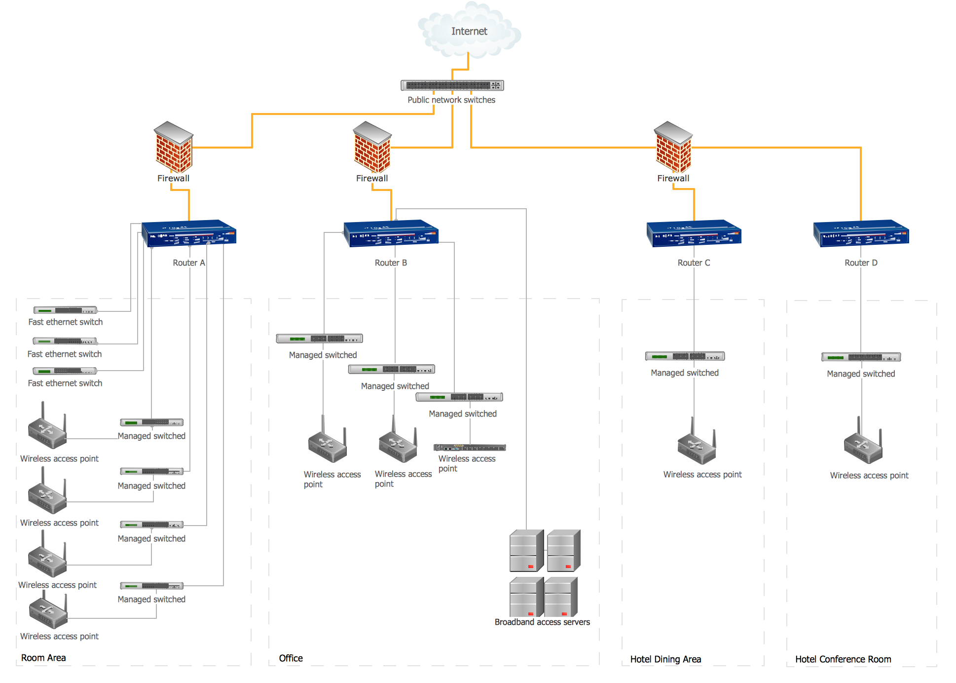
Picture: Hotel Network Topology Diagram
Related Solution:
In general, you can use any icons to represent network equipment on a diagram. However, there are some icons, for instance, Cisco icons, shapes, stencils and symbols, that are recognizable worldwide. Using those icons you can create Cisco network topology diagrams in minutes and share them anywhere.
The icons depicting Cisco network equipment are recognized and generally applied as standard images for designing network diagrams. They are free to used , but can not be reworked. Cisco network diagrams are created to depict how signals processed on the network equipment and end-user computers and how data transfer through LAN or WLAN between nodes. The vector graphic library of ConceptDraw CISCO Network Diagrams solution includes about 90 icons of Cisco network equipment for designing computer network diagrams with ConceptDraw DIAGRAM.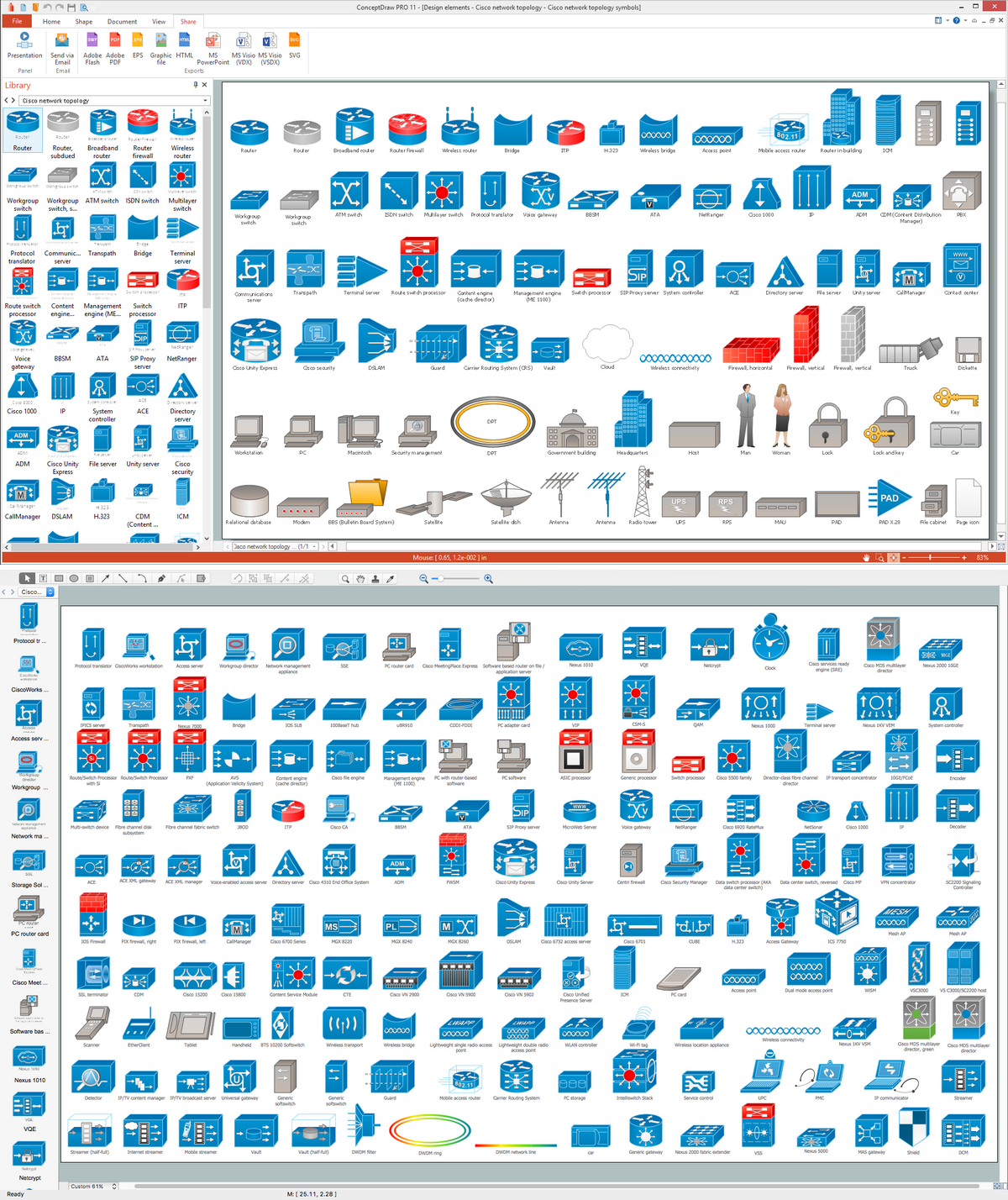
Picture: Cisco Network Topology. Cisco icons, shapes, stencils and symbols
Related Solution:
Computer networks nowadays are spread all across the world. The large number of parameters, such as geographic scale or communication protocols, can divide networks. One of the most common types of networks is called local area network (LAN). It convenient to represent network examples by means of diagrams.
This local area network (LAN) diagram provides an easy way to see the way the devices in a local network are interacted. The diagram uses a library containing specific symbols to represent network equipment , media and the end-user devices such as computers (PC, mac, laptop) , network printer, hubs, server and finally a modem. There are two types of network topologies: physical and logical. The current diagram represents precisely a physical type of LAN topology because it refers to the physical layout of a local network equipment.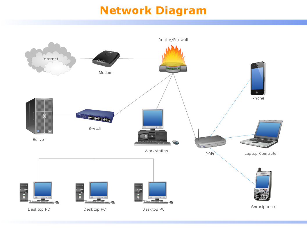
Picture:
What is a Local Area Network?
Examples of LAN Diagrams
Related Solution:
If you have a small budget to design a computer network, you have to be very careful. One of the most cheap technologies to implement is a bus network topology, however it has many disadvantages. For instance, if the network cable is somehow damaged, the entire network won't work.
This diagram illustrates a so-called "Bus" network topology. This type of network arrangement means that each computer or other device is linked to a main link (bus). The end nodes are shown as a circle. The links to the bus are depicted as solid vertical lines. The bus is shown as a bold horizontal line. This diagram can serve as a template for creating logical or physical network diagrams. The set of vector libraries supplied with ConceptDraw Computer and Networks solution contains the symbols of all LAN and WLAN elements required for creating network diagrams of any configuration.
Picture: Bus Network Topology
Related Solution:
Every corporate network is unique, though there are guidelines and best practices in developing networks. As it is quite difficult to implement a pure topology within a company, using a hybrid network topology is considered a better solution. As a rule, such network assembles advantages and features of source topologies.
This diagram is an example of the Hybrid network. This type of network topology means a conjunction of other network topologies. Such as star-bus, ring-mesh topologies, etc. It should be obviously diverse networks. The final computer network inherits both advantages and disadvantages of its ingredients. Using the ConceptDraw Computer and Networks solution including vector graphic libraries and templates one can develop professional custom network diagrams of any topology and complexity.
Picture: Hybrid Network Topology
Related Solution:
There are several basic topologies including bus, star, point-to-point, ring and a hybrid. Two computers can form a fully connected network topology, and as the number of network nodes increases, the network diagram gets more complicated. This type of topology is also called a full mesh.
This is a visual example of a computer network built using a mesh topology. This diagram presents the schematic structure of the full mesh network topology. A common mesh network topology means that each network device is connected with several points in the network, so if the one node of the network goes down, it does not cause an issue with an operability of the entire computer network. In a full mesh network topology, every computer or device in the network is interconnected with each of the other devices in the network.
Picture: Fully Connected Network Topology Diagram
Related Solution: