Wiring Diagrams with ConceptDraw DIAGRAM
A wiring diagram is a comprehensive diagram of each electrical circuit system showing all the connectors, wiring, terminal boards, signal connections (buses) between the devices and electrical or electronic components of the circuit. It also identifies the wires by wire numbers or colour coding. Wiring diagrams are necessary to troubleshoot and fix electrical or electronic circuits.
To draw such diagram which helps to identify the wires by color coding or wire numbers is simple with help of ConceptDraw DIAGRAM which can be used together with vector symbols and special elements from numerous libraries as well as using our templates designed in advance in order to provide you with so many different choices of examples. Find our 26 libraries with 926 electrical symbols to make your own sophisticated great looking wiring diagrams and to make it possible to use software for other purposes in case you get used to it and it will happen very soon as our product is simple to use. Try today to be much better at utilizing it tomorrow in order to succeed and to make your business prospering.
Pic. 1. Wiring Diagram with ConceptDraw DIAGRAM
A circuit diagram makes use of standardized symbols that represent electrical components or devices. It is easier to draw these symbols than drawing the concrete pictures of the components.
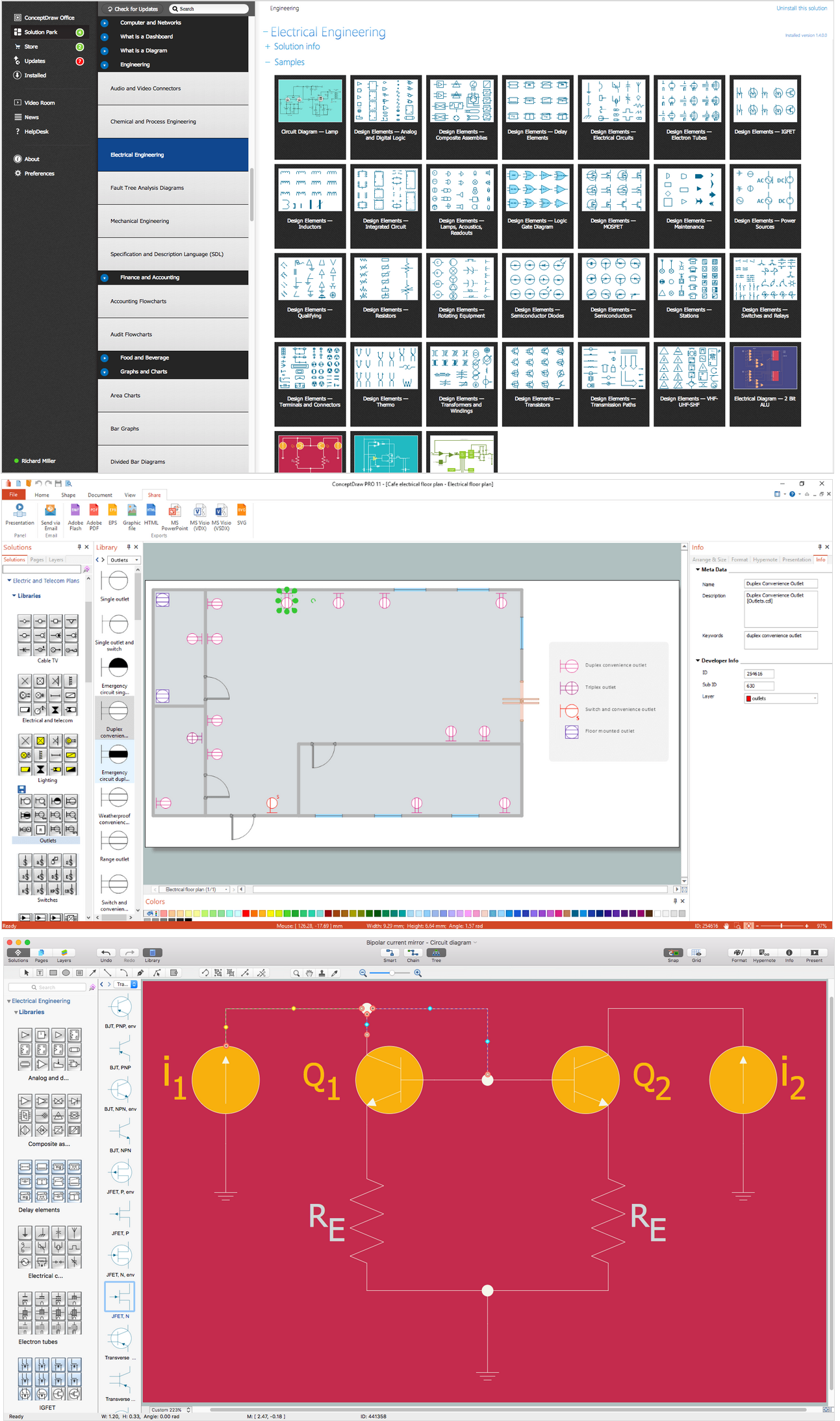
The graphics elements found in the Electrical Engineering solution can help you design electrical schematics, circuit and wiring blueprints, power systems diagrams, and maintenance and repair diagrams.
26 libraries, 926 electrical schematic symbols from electrical engineering.

Analog and Digital Logic symbols

Electrical and Telecom Symbols

Delay Elements symbols

Electrical Circuits symbols

Electron Tubes symbols

IGFET symbols

MOSFET symbols

Maintenance symbols

Lamps Acoustics Readouts symbols

Logic Gate Diagram symbols

Integrated Circuit symbols

Inductors symbols
The actual components might change appearance as the electronics industry revises them or renders them obsolete. The diagrams describe the way in which the components are connected electrically. There are drawn lines that stand for wires or conductors between the appropriate connection points on the symbols; no particular type of wire or physical distance between components is implied; two components might be separated by a few inches or centimeters or a meter or feet.
Pic. 2. Wiring Diagram
The graphics elements found in the Electrical Engineering solution can help you design electrical schematics, circuit and wiring blueprints, power systems diagrams, and maintenance and repair diagrams.
Using ConceptDraw DIAGRAM professional software for making wiring diagrams.
ConceptDraw DIAGRAM intended for creating wide variety range of wiring diagrams. These applications described in Industrial Engineering Area of ConceptDraw Solution Park.
House Electrical Diagram or House Wiring Diagram. It shows electrical circuits or put wires on the floor plan or house or building - let you create wiring diagram on a floor plan. The software features making a diagrams of weak-current installations, light-current systems and power circuits. All the tools for making wiring diagrams: graphical symbols collected in electrical stencils and located in ConceptDraw Solution Park, Design Elements of Electrical Engineering solution.
TEN RELATED HOW TO's:
When trying to figure out the nature of the problems occurring within a project, there are many ways to develop such understanding. One of the most common ways to document processes for further improvement is to draw a process flowchart, which depicts the activities of the process arranged in sequential order — this is business process management. ConceptDraw DIAGRAM is business process mapping software with impressive range of productivity features for business process management and classic project management. This business process management software is helpful for many purposes from different payment processes, or manufacturing processes to chemical processes. Business process mapping flowcharts helps clarify the actual workflow of different people engaged in the same process. This samples were made with ConceptDraw DIAGRAM — business process mapping software for flowcharting and used as classic visio alternative because its briefly named "visio for mac" and for windows, this sort of software named the business process management tools.
This flowchart diagram shows a process flow of project management. The diagram that is presented here depicts the project life cycle that is basic for the most of project management methods. Breaking a project into phases allows to track it in the proper manner. Through separation on phases, the total workflow of a project is divided into some foreseeable components, thus making it easier to follow the project status. A project life cycle commonly includes: initiation, definition, design, development and implementation phases. Distinguished method to show parallel and interdependent processes, as well as project life cycle relationships. A flowchart diagram is often used as visual guide to project. For instance, it used by marketing project management software for visualizing stages of marketing activities or as project management workflow tools. Created with ConceptDraw DIAGRAM — business process mapping software which is flowcharting visio alternative or shortly its visio for mac, this sort of software platform often named the business process management tools.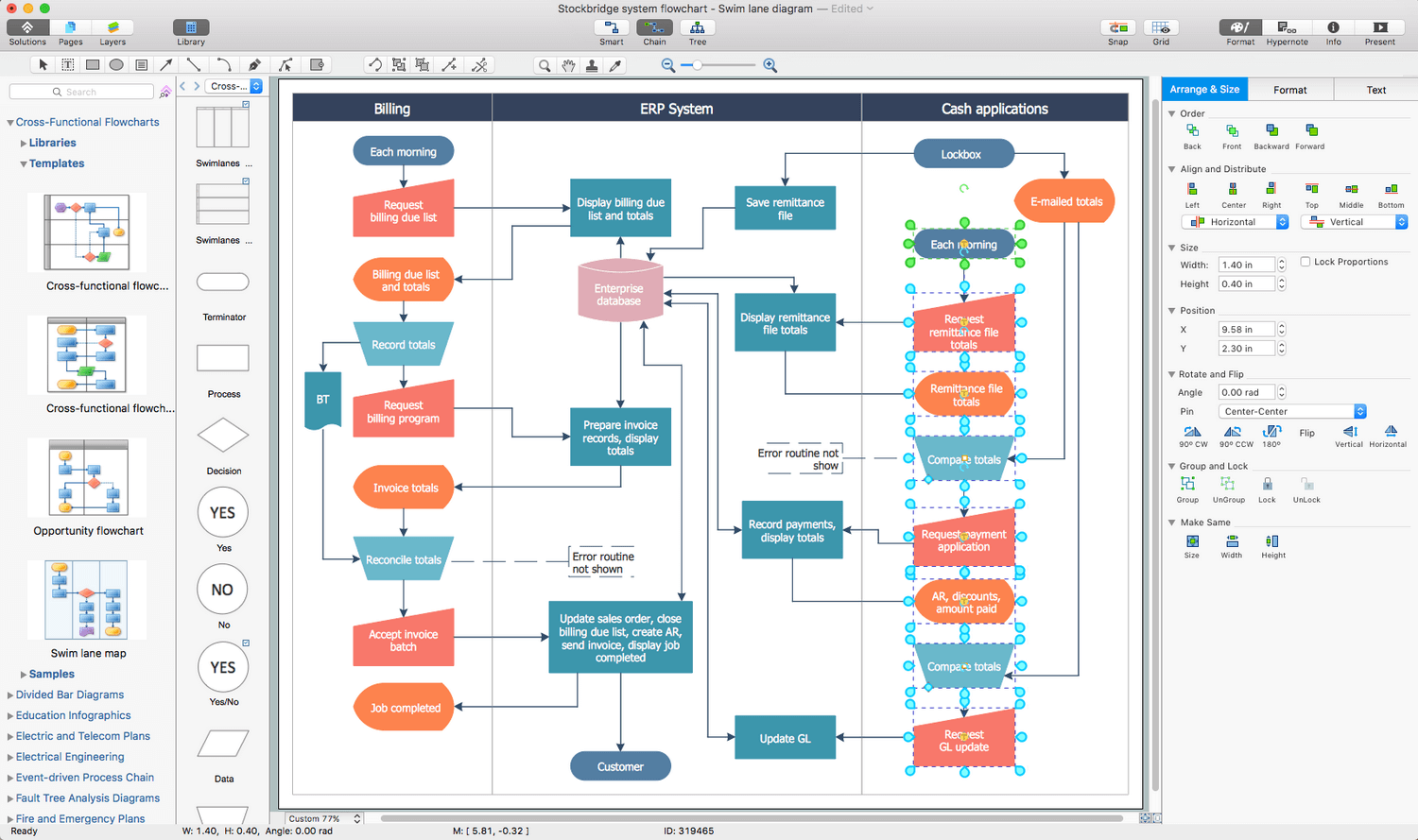
Picture: Process Flowchart: A Step-by-Step Comprehensive Guide
Related Solution:
Electrical Engineering Solution used together with ConceptDraw DIAGRAM drawing facilities makes short a work of drawing various electrical and electronic circuit schemes. A library of vector objects composed from symbols of Analog and Digital Logic elements of electric circuit includes 40 symbolic images of logic gates, bistable switches of bi-stable electric current, circuit controllers, amplifiers, regulators, generators, etc. All of them can be applied in electronic circuit schemes for showing both analog and digital elements of the circuit.
Electrical Engineering Solution used together with ConceptDraw DIAGRAM drawing facilities makes short a work of drawing various electrical and electronic circuit schemes. A library of vector objects composed from symbols of Analog and Digital Logic elements of electric circuit includes 40 symbolic images of logic gates, bistable switches of bi-stable electric current, circuit controllers, amplifiers, regulators, generators, etc. All of them can be applied in electronic circuit schemes for showing both analog and digital elements of the circuit.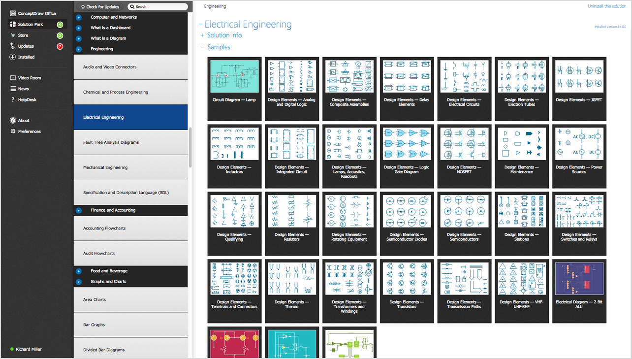
Picture:
Electrical Diagram Symbols F.A.Q.
How to Use Electrical ConceptDraw Diagram Software
Related Solution:
The Audio & Video Connectors solution contains a set of pre-designed objects, libraries, templates, and samples; allowing quick and easy diagramming of various configurations of audio and video devices.
Picture: Audio & Video Connector Types
Related Solution:
The Audio & Video Connectors solution contains a set of pre-designed objects, libraries, templates, and samples; allowing quick and easy diagramming of various configurations of audio and video devices.
Picture: Audio Visual Connectors Types
Related Solution:
Electrical plan is a document that is developed during the first stage of the building design. This scheme is composed of conventional images or symbols of components that operate by means of electric energy. To simplify the creation of these schemes you can use house electrical plan software, which will not require a long additional training to understand how to use it. You only need to install the necessary software ant it’s libraries and you’ll have one less problem during the building projection.
Any building contains a number of electrical systems, including switches, fixtures, outlets and other lightening equipment. All these should be depicted in a building electrical plans and included to general building documentation. This home electrical plan displays electrical and telecommunication devices placed to a home floor plan. On the plan, each electrical device is referenced with the proper symbol. Electrical symbols are used for universal recognition of the building plan by different persons who will be working on the construction. Not all possible electric symbols used on a certain plan, so the symbols used in the current home plan are included to a legend. The electrical home plan may be added as a separate document to a complete set of building plans.
Picture: How To use House Electrical Plan Software
Related Solution:
You need design Electrical Schematic and dream to find the useful tools to draw it quick and easy? ConceptDraw DIAGRAM offers the unique Electrical Engineering Solution from the Industrial Engineering Area which will effectively help you!
Picture: Electrical Schematic
Related Solution:
Electronic components have two or more electrical terminals (or leads) aside from antennas which may only have one terminal. These leads connect to create an electronic circuit with a particular function (for example an amplifier, radio receiver, or oscillator). Basic electronic components may be packaged discretely, as arrays or networks of like components, or integrated inside of packages such as semiconductor integrated circuits, hybrid integrated circuits, or thick film devices.
26 libraries of the Electrical Engineering Solution of ConceptDraw DIAGRAM make your electrical diagramming simple, efficient, and effective. You can simply and quickly drop the ready-to-use objects from libraries into your document to create the electrical diagram.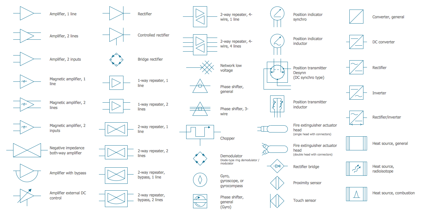
Picture: Electrical Symbols — Composite Assemblies
Related Solution:
ConceptDraw DIAGRAM software is a great assistant in electrical engineering and electrical design. It is efficient in creating ✔️ complex and simple electrical designs, ✔️ power generation, transmission, and distribution electrical schematics, ✔️ transformers diagrams, ✔️ electrical schematics with transformers
Picture: Electrical Symbols — Transformers and Windings
Related Solution:
No building project can exist without an electrical circuit map. It’s more convenient to develop electrical drawing with a proper software which would contain vector shapes and electrical symbols. This will help in the future if any problems appear.
This circuit diagram shows the scheme of a location of components and connections of the electrical circuit using a set of standard symbols. It can be use for graphical documentation of an electrical circuit components. There are many of different electric circuit symbols that can be used in a circuit diagram. Knowing how to read circuit diagrams is a useful skill not only for professionals, but for any person who can start creating his own small home electronic projects.
Picture: Electrical Drawing Software and Electrical Symbols
Related Solution:
Computer networks nowadays are spread all across the world. The large number of parameters, such as geographic scale or communication protocols, can divide networks. One of the most common types of networks is called local area network (LAN). It convenient to represent network examples by means of diagrams.
This local area network (LAN) diagram provides an easy way to see the way the devices in a local network are interacted. The diagram uses a library containing specific symbols to represent network equipment , media and the end-user devices such as computers (PC, mac, laptop) , network printer, hubs, server and finally a modem. There are two types of network topologies: physical and logical. The current diagram represents precisely a physical type of LAN topology because it refers to the physical layout of a local network equipment.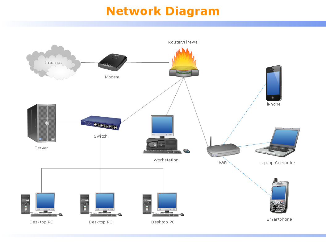
Picture:
What is a Local Area Network?
Examples of LAN Diagrams
Related Solution:
 Analog and Digital Logic symbols
 Electrical and Telecom Symbols
 Delay Elements symbols
 Electrical Circuits symbols
 Electron Tubes symbols
 IGFET symbols
 MOSFET symbols
 Maintenance symbols
 Lamps Acoustics Readouts symbols
 Logic Gate Diagram symbols
 Integrated Circuit symbols
 Inductors symbols
