Amazon Web Services Diagrams
diagramming tool for architecture
The AWS Architecture Diagrams solution includes icons, sample and templates for several Amazon Web Services products and resources, to be used when creating architecture diagrams. The icons are designed to be simple so that you can easily incorporate them in your diagrams and put them in your whitepapers, presentations, datasheets, posters or any technical material you like.
For IT specialists, system designers and network administrators, the AWS Architecture Diagrams solution offers a wide range of recognizable graphic icons to help illustrate a diagram, as well as a helpful selection of templates and samples to model a design on. Architecture diagrams are a great way to communicate your design, deployment and topology. Here you will find an official collection of AWS resources that will help you build great AWS Architecture diagrams.
"The AWS Architecture Center is designed to provide you with the necessary guidance and application architecture best practices to build highly scalable and reliable applications in the AWS cloud. These resources will help you understand the AWS platform, its services and features, and will provide architectural guidance for design and implementation of systems that run on the AWS infrastructure."
ConceptDraw - Diagramming Tool for:
- Create Web Application Architecture
- Architect infrastructure based on AWS® (Amazon Web Services)
- Design application services based on AWS® (Amazon Web Services)
- Design auto-scalable architecture
- Design for elastic compute cloud
- Create Amazon Web Services planning diagrams
- Illustrate whitepapers and presentations
- Create vector graphics files
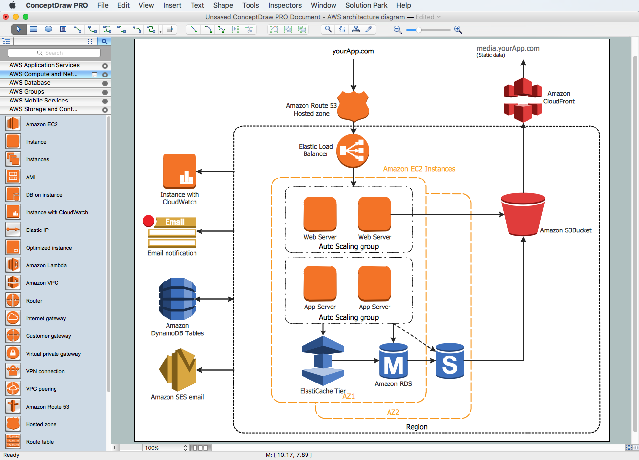 This diagram was created in ConceptDraw® PRO using the AWS® Architecture Diagram library from the Amazon Web Services Architecture Diagrams solution (AWS solution).
See also:
-
Diagramming software for Amazon Web Service
Diagrams, charts, schemes, symbols and icons -
AWS Simple Icons for Architecture Diagrams
Diagramming for Amazon Web Services architecture - Design Elements and Icons - Samples
Network Diagrams — AWS Architecture
NINE RELATED HOW TO's:Any business process consists from a number of tasks carrying out the certain business goal. It is useful to diagram business processes to ensure that they are as foolproof, logical and sequential as possible. This business process diagram describes a typical booking process flow by the example of a cab booking process. It can be used as a roadmap for any booking system implementation. Diagramming a business process allows you to look at the entire project and take into account all types of possible scenarios. Business process diagram helps you investigate and clarify the process thoroughly so that you can find out how it can be improved. Business process diagram supports team communications by ensuring that each process element is clear and everyone in the team is on the same page. Sometimes your company brings you less profit than you expect it to be, and it’s difficult to reveal the causes. Maybe it’s time to learn new technologies, because business diagram are easily developed by means of special software, so you won’t make any extra effort. In return, you will increase your productivity and get more done in a less time. Picture: Business Diagram SoftwareRelated Solutions:UML Component Diagram Online Shopping. This sample was created in ConceptDraw DIAGRAM diagramming and vector drawing software using the UML Component Diagram library of the Rapid UML Solution from the Software Development area of ConceptDraw Solution Park. This sample shows the concept of the online shopping and is used for the understanding of the online shopping processes, of the online shops working processes, for projection and creating of the online stores.
 Picture: UML Component Diagram Example - Online ShoppingRelated Solution:This sample was created in ConceptDraw DIAGRAM diagramming and vector drawing software using the Flowcharts solution from the Diagrams area of ConceptDraw Solution Park. This sample shows the Flowchart that displays the procedures of 2PP (two-party preferred) voting and counting the voters. The two-party-preferred vote is the result of the elections that was distributed to the final two parties.
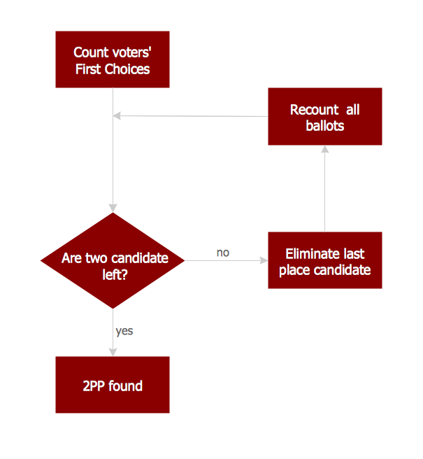 Picture: Basic Flowchart Images. Flowchart ExamplesRelated Solution:The best way to visualize the introduction to Cloud computing architecture is to create diagrams and schematics representing what is a cloud computing and how it works. For their design, we recommend to use a powerful ConceptDraw DIAGRAM diagramming and vector drawing software supplied with Cloud Computing Diagrams solution from the Computers and Network area of ConceptDraw Solution Park
 Picture: Introduction to Cloud Computing ArchitectureRelated Solution:In general, you can use any icons to represent network equipment on a diagram. However, there are some icons, for instance, Cisco icons, shapes, stencils and symbols, that are recognizable worldwide. Using those icons you can create Cisco network topology diagrams in minutes and share them anywhere. The icons depicting Cisco network equipment are recognized and generally applied as standard images for designing network diagrams. They are free to used , but can not be reworked. Cisco network diagrams are created to depict how signals processed on the network equipment and end-user computers and how data transfer through LAN or WLAN between nodes. The vector graphic library of ConceptDraw CISCO Network Diagrams solution includes about 90 icons of Cisco network equipment for designing computer network diagrams with ConceptDraw DIAGRAM.
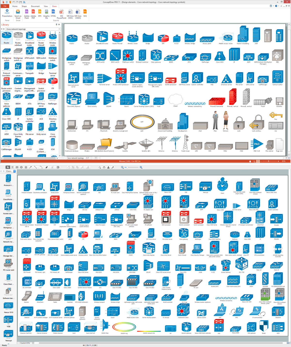 Picture: Cisco Network Topology. Cisco icons, shapes, stencils and symbolsRelated Solution:UML Component Diagrams are used to illustrate the structure of arbitrarily complex systems and illustrates the service consumer - service provider relationship between components.
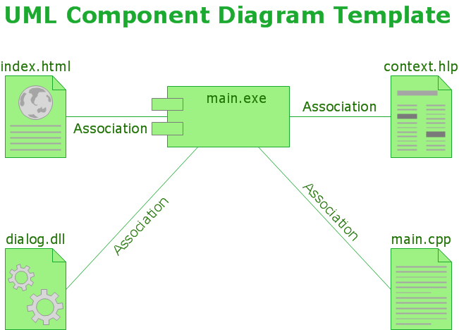 Picture: UML Component DiagramConceptDraw DIAGRAM is a powerful diagramming and vector drawing software. Extended with Website Wireframe solution from the Software Development area, ConceptDraw DIAGRAM became the ideal software for prototype and design professional looking websites wireframes. Website Wireframe solution offers at your disposal wide variety of wireframe examples and samples which confirm this.
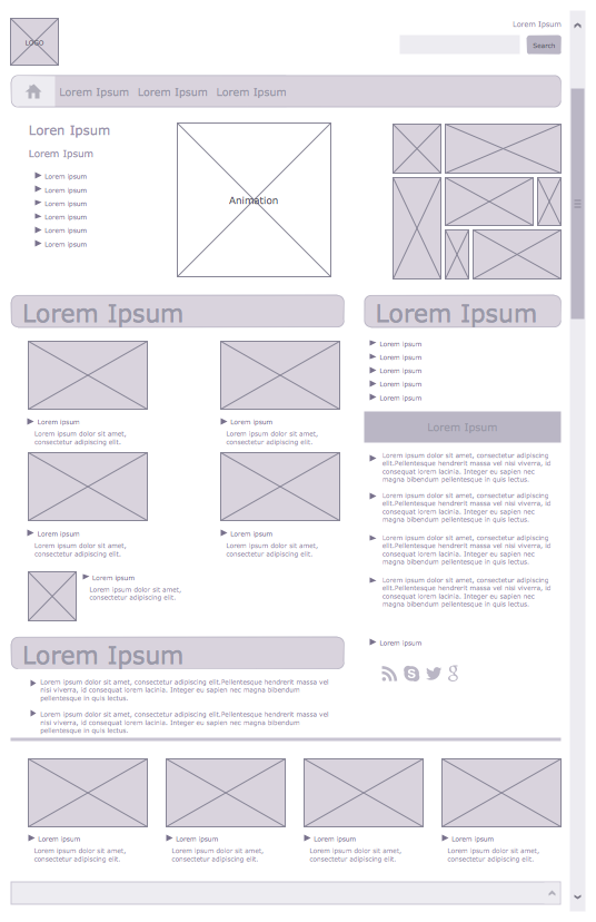 Picture: Wireframe ExamplesRelated Solution:Local area network connects computers and other network appliances within an area, such as office building or a campus. It can be difficult to provide such network without a predesigned plan. For these purposes you can use network diagram software, which helps you to create LAN network diagrams and office network diagrams quickly and effortless. This will speed up your work and you can save the diagram for the future network improvements. The following diagram illustrates a network topology of the small office. LAN configuration has a star topology. The local network joins 8 computers among which are several desktop PCs, laptop, two iMacs and iBook. The end-point devices are divided into three groups. Each group is connected to its hub. There is a network printer and a modem, which are interconnected with other devices through a network server. Each computer on the LAN can access the server through a corresponding hub.
 Picture: Network Diagram Software. LAN Network Diagrams. Physical Office Network DiagramsRelated Solution:ConceptDraw DIAGRAM extended with Enterprise Architecture Diagrams Solution from the Management Area is a powerful software which provides a set of helpful tools for designing Information Technology Architecture.
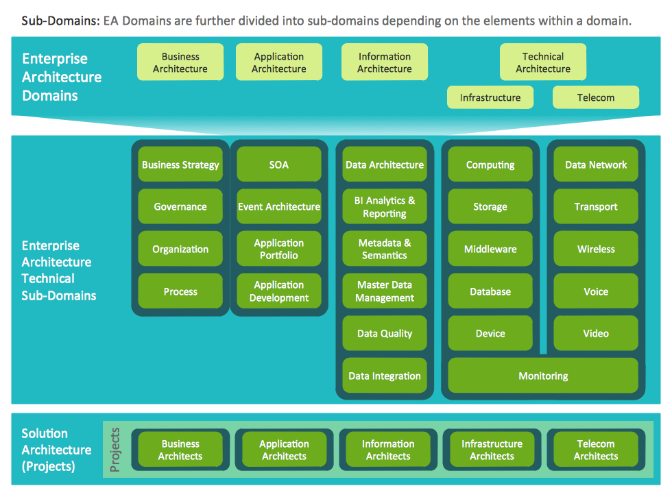 Picture: Information Technology ArchitectureRelated Solution:ConceptDrawDIAGRAM 18