Bus Network Topology
Bus Network Topology Diagram
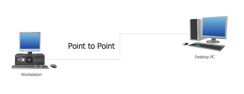
There is one of the most commonly used computer network topologies – bus network topology. Bus networks are well known for their nodes being located in a shape of a bus. The way such networks look reminds of a bus as the nodes in it are connected to one common linear, which is called a bus.
In this diagram of a form of a bus everyone can clearly see both the linear, the nodes and them directly connected to that linear.
There is a host on a bus, which is called a “Station”. It can also be called as a “Workstation”. Every of the “stations” or “workstations” receive all of the network traffic which is generated by each of such stations and has equal transmission priority. The nodes in such topology transmit the data at the same time as they work simultaneously by using the so called media access control technology. The example of such media access control technology can be a carrier sense multiple access as well as a bus master.
There are many advantages of such bus network topology, as it is always very simple to connect a computer or peripheral to a linear bus and it always requires less cable length than a star topology, which results in lower costs of having such topology. Also bus network topology within networks are simpler to extend by joining cable with connector or repeater. Any of the existing bus network topologies work better for small networks which can be also a disadvantage in case yours is quite large. Other disadvantages are: large amount of packet collisions on one network which results in high amounts of packet loss and the possibility of the network to be shut down in case there is a break in the main cable or in case one of the T connectors breaks. But, again, the good thing is that in this topology data being transferred may be accessed by any workstation.
There are two types of the bus network topologies, one of which is a “Linear bus” one. This type of network topology is the one where all of the nodes of the entire network are connected to one common transmission with only two endpoints. In this type of bus topology all of the data transmitted between nodes is transmitted over this common transmission medium and it is able to be received by all nodes at the same time. Another type of bus network topology is called “Distributed bus”. This type of network topology is the one, where all of the network nodes are connected to one common transmission medium and where this transmission medium has more, than two endpoints, which are created by adding the branches to the main section of the transmission medium.
If you work in IT or you, for some reason, want to illustrate the way bus network topology looks like and you want to make this drawing look truly professional, then you might spend long hours trying to create it yourself. Although, there is another option. If you find the right software to be able to use it in order to create such great looking, smart, professional bus network topology diagram, then it can be much simpler to finish with your drawing and so quicker.
We always recommend to use only the best software possible which is ConceptDraw DIAGRAM This software is a very special one and only the reason it was developed by the IT specialists from CS Odessa with experience in drawing charts, flowcharts, diagrams and schemes makes it so special. This application allows ConceptDraw DIAGRAM users to choose any of the available solutions full of stencil libraries with proper design elements as well as pre-made examples and templates of so many graphs, charts, plans, schemes, flowcharts and diagrams created by the team of CS Odessa IT specialists.
Having all of the options to use, including different solutions where you can always find the necessary tools, such as the design elements to use for your own great looking drawings or the existing examples as well as templates and layouts of the previously made drawings which you can always use as drafts for your own drawings, is always very beneficial. In case you decide to get one of the solutions after downloading ConceptDraw DIAGRAM you can always download them either from the ConceptDraw STORE which is another product of CS Odessa, or this site. Each of the solutions provide at least one library with the stencils that can be used for making so many different charts, plans, schemes, flowcharts and diagrams, including the star network topology ones.
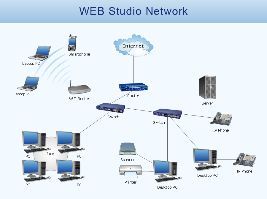
Having them means having pretty much everything you need to make it happen – to make a smart looking bus network topology diagram from a scratch using Computer and Networks solution from Computer and Networks area of ConceptDraw Solution Park which provides examples, templates and vector stencils library with symbols of local area network (LAN) and wireless LAN (WLAN) equipment.
You can always use it to draw the physical and logical network topology diagrams for wired and wireless computer communication networks, including the “Linear bus” and the “Distributed bus”.
No matter which of the mentioned above types of the computer network topology diagrams you want to create, you can always do it within only a couple of hours or even minutes, depending on your general experience of using ConceptDraw DIAGRAM software. Download it today in case you still do not have this unique and very convenient application and use it for making your own diagrams, great looking plans, schemes, charts and flowcharts.
Once you try and succeed in creating something special and professionally looking, then we doubt that you will stop using this unique software, but will recommend to those who do not have it yet and so somebody else will have a change to get this application and so simplify their work with drawing the schemes, charts, plans, diagrams and flowcharts.

Pic. 1. Bus Network Topology
Use it to draw the physical and logical network topology diagrams for wired and wireless computer communication networks.

Pic. 2. Bus Network Topology Diagram
Download ConceptDraw DIAGRAM already today to have a chance to create your first great looking drawing. Do not forget to get also ConceptDraw STORE so you have all of the tools developed and provided by CS Odessa team of IT specialists.
See Also Network Topologies:
- Star Network Topology
- Ring Network Topology
- Mesh Network Topology
- Tree Network Topology
- Fully Connected Network Topology


_Win_Mac.png)
