Example 1. Workflow diagram symbols
Workflow diagram lets to represent the transferring of data, documents, and tasks during performance of a work process, helps show relashionships between process steps and understand the complete process, identify critical stages and problem areas. The Workflow Diagrams solution extends ConceptDraw DIAGRAM software with samples, templates and library of instantly recognizable vector stencils for effectively drawing Workflow diagrams.

Example 2. Business Workflow Diagram
Use workflow flowcharts to analyze the work processes, to show the path of the tasks, the responsible persons and the associated documents, to identify required resources, to optimize a workflow, and to discover its inherent weak points.
Follow the next steps to design any Workflow Diagram:
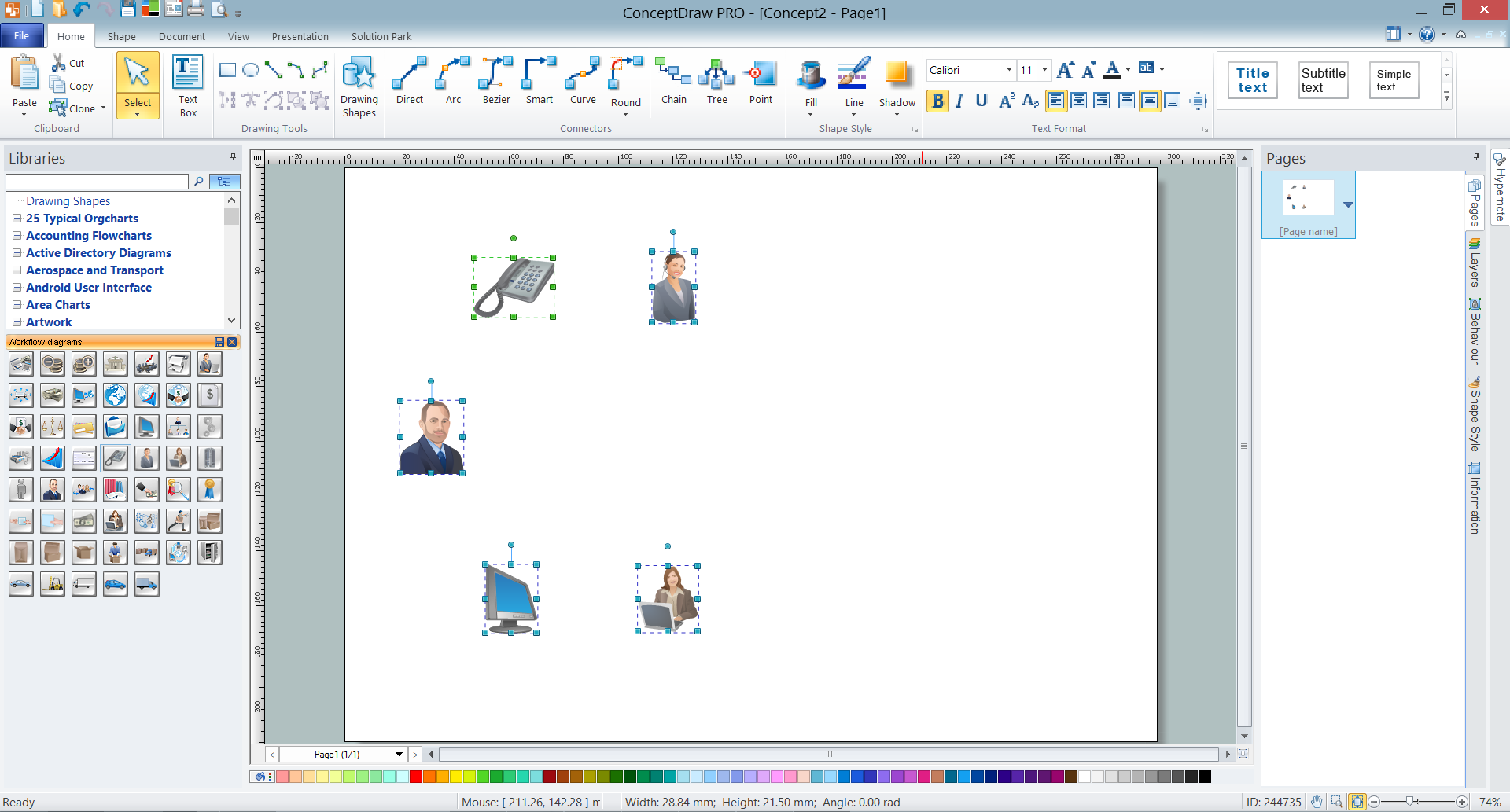
- add desired workflow objects from the Workflow Diagram library by dragging them from the Work Flow Diagram library to the document page;

Example 3. Adding Workflow Objects
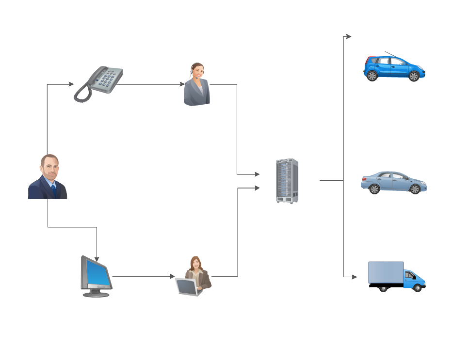
- arrange the objects and connect them with arrows using the connector tools from the ConceptDraw's Home toolbar, it is convenient to use the Smart connector and drag the connector from one connect dot to another;

Example 4. Connecting Objects
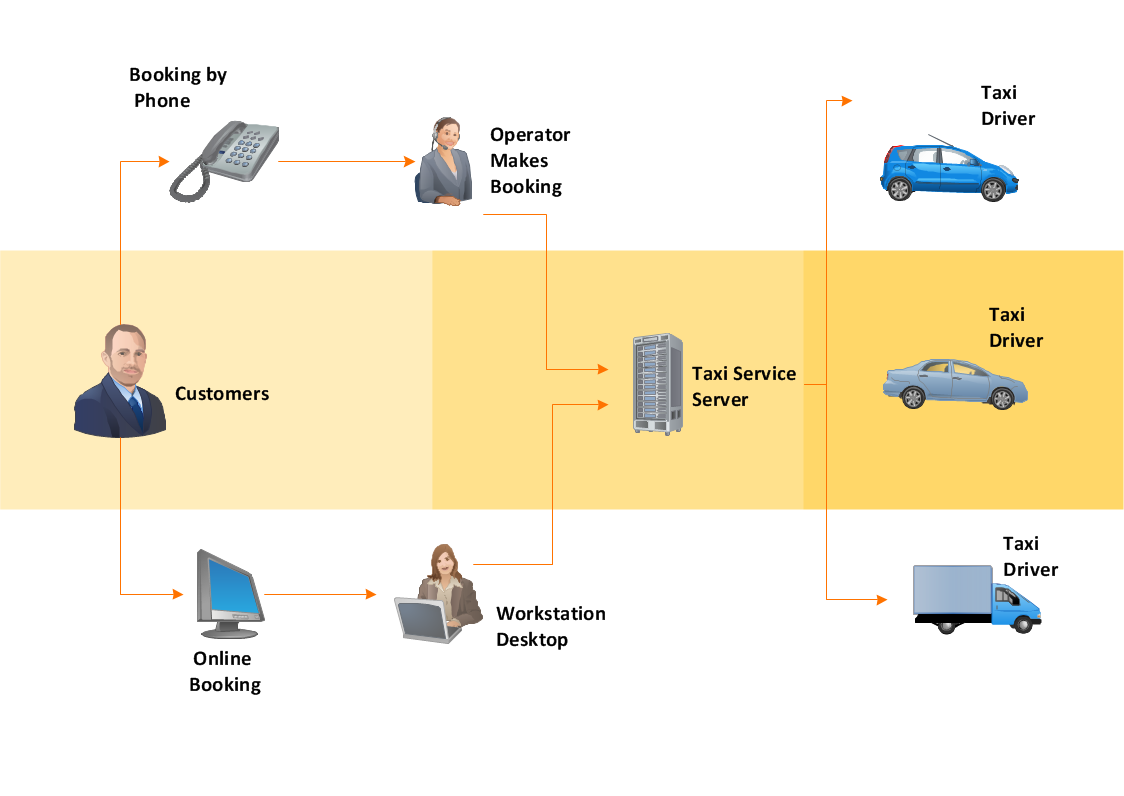
- type the text, resize the objects if needed and recolor connectors according to your taste.

Example 5. Workflow Diagram - Taxi Service
Another way is to start with ready Workflow Diagram template also included to Workflow Diagrams solution and offered by ConceptDraw STORE. When modifying template, use also symbols from the variety offered by Workflow Diagrams library to represent different types of actions and the steps in a workflow, among them are the objects of persons, accounting, bank, accounts receivable and payable, customer service, manufacturing, marketing, distribution, quality assurance, and more others.

Example 6. Workflow Diagram Solution (Mac OS X and Windows)
When it comes to creating a Workflow Diagram, it's important to use software that is capable of describing a wide range of processes, using easily recognizable techniques and graphical notation. An ideal drawing platform will utilize functions that can cope with the output of a high volume of processes, that may change rapidly from development to implementation stages. ConceptDraw DIAGRAM software, with the extended functionality of the Workflow Diagrams solution, is the ideal medium for creating even the most complex designs of this type.
TEN RELATED HOW TO's:
Process Flow Charts are very popular and widely used in chemical and process engineering for representation a general flow of plant processes and equipment. If you need often draw them, the ConceptDraw DIAGRAM diagramming and vector drawing software extended with tools of Flowcharts Solution will be useful for you.
The mostly used set of process flow chart symbols includes the following: Rectangle (box) process flow chart symbol, Rounded rectangle, Circle, Diamond.
Picture: Process Flow Chart Symbol
Related Solution:
Accounts Payable Flowchart - There is nothing easier than do it in ConceptDraw DIAGRAM. ConceptDraw DIAGRAM diagramming and vector drawing software provides the Accounting Flowcharts Solution from the Finance and Accounting Area of ConceptDraw Solution Park.
The Accounting Flowcharts Solution contains templates, samples and library of ready-to-use predesigned vector objects that will help you create: accounts payable flowchart, accounts payable process flow chart, accounting flowchart of any complexity quick and easy.
Picture: Accounts Payable Flowchart
Related Solution:
The UML diagram is a powerful tool which lets visually represent all system's components, the interactions between them and relationships with external user interface.
The Rapid UML solution for ConceptDraw DIAGRAM software offers diversity of UML flowchart symbols for drawing all types of UML diagrams.
Picture: UML Flowchart Symbols
Related Solution:
Venn diagrams are illustrations used in the branch of mathematics known as set theory.
Use ConceptDraw DIAGRAM to quick and easy design your own Venn Diagram of any complexity.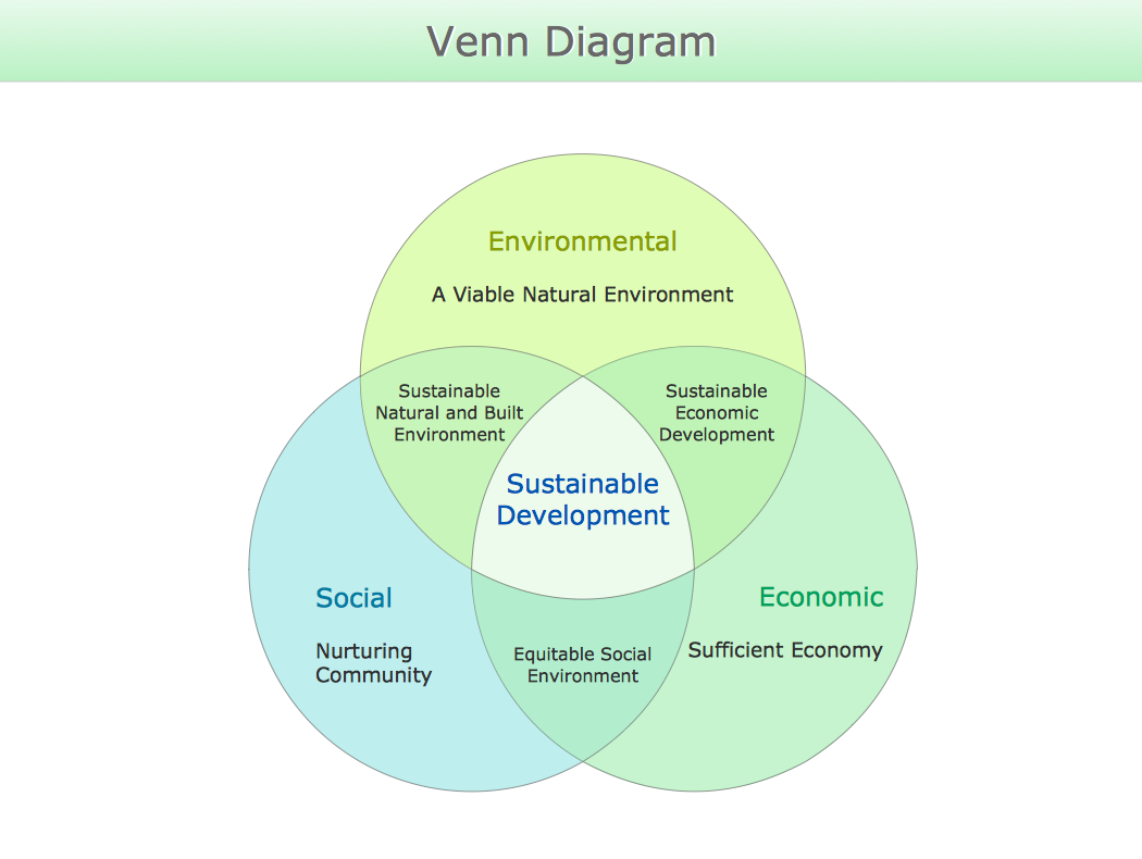
Picture: Venn Diagram
Related Solution:
Users new to ConceptDraw PROJECT will find the Basic lessons an essential platform for familiarizing themselves with the program′s functions. This video lesson will teach you how to set up task trees and dependencies.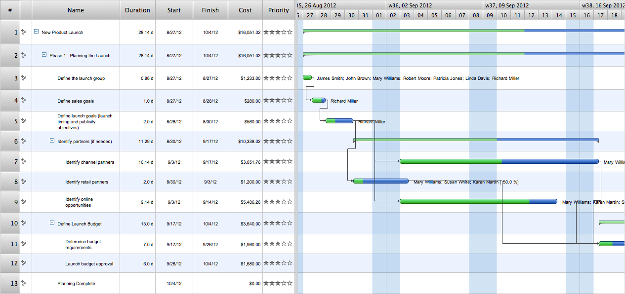
Picture: Project —Task Trees and Dependencies
Program Structure Diagram is a visual representation of a program's organization, showing its components and their relationships.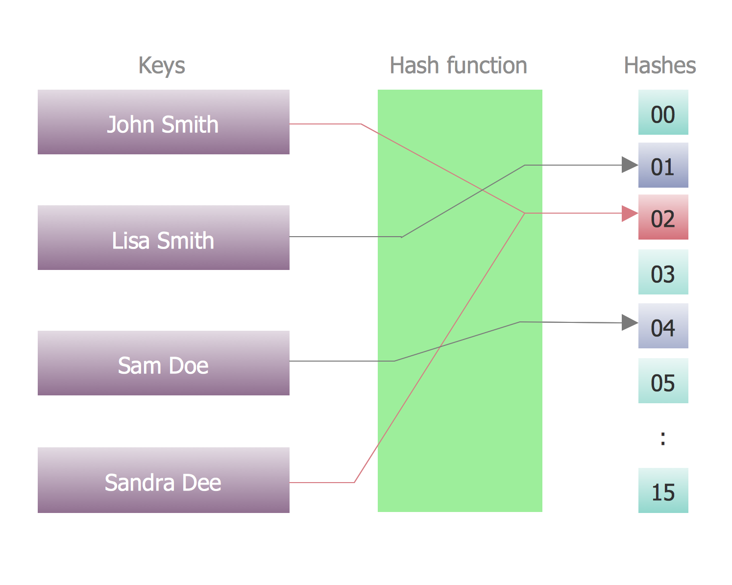
Picture: Program Structure Diagram
Block diagrams solution extends ConceptDraw DIAGRAM software with templates, samples and libraries of vector stencils for creating the block diagram.
Create block diagrams, electrical circuit diagrams, schematics, and more in minutes with ConceptDraw DIAGRAM.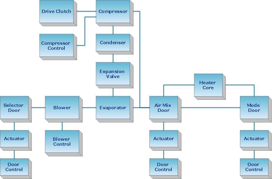
Picture: Create Block Diagram
Learn about Systems Engineering, its process and discover practical examples illustrated through diagrams. ✔️ How to draw Systems Engineering diagrams using the ConceptDraw DIAGRAM software?
Picture:
What is a Systems Engineering?
Examples of Systems Engineering Diagrams
Related Solution:
Local area network connects computers and other network appliances within an area, such as office building or a campus. It can be difficult to provide such network without a predesigned plan. For these purposes you can use network diagram software, which helps you to create LAN network diagrams and office network diagrams quickly and effortless. This will speed up your work and you can save the diagram for the future network improvements.
The following diagram illustrates a network topology of the small office. LAN configuration has a star topology. The local network joins 8 computers among which are several desktop PCs, laptop, two iMacs and iBook. The end-point devices are divided into three groups. Each group is connected to its hub. There is a network printer and a modem, which are interconnected with other devices through a network server. Each computer on the LAN can access the server through a corresponding hub.
Picture: Network Diagram Software. LAN Network Diagrams. Physical Office Network Diagrams
Related Solution:
This sample was created in ConceptDraw DIAGRAM diagramming and vector drawing software using the UML Deployment Diagram library of the Rapid UML Solution from the Software Development area of ConceptDraw Solution Park.
This sample shows the work of the ATM (Automated Teller Machine) banking system that is used for service and performing of the banking transactions using ATMs. System engineers can use comprehensive UML diagrams solution.
Picture: UML Deployment Diagram Example - ATM SystemUML diagrams
Related Solution: