Circuit Diagrams
A Circuit diagram is a graphical representation of an electrical circuit and an electrical current. It uses simple standardized symbols to show the components and interconnections in a circuit. These symbols reflect features of the physical construction of the devices. Typically, an electronic circuit includes electronic components like switches, resistors, diodes, batteries, and more connected by conductive wires through which an electric current flows.
A Circuit diagram gives a clear presentation of a circuit and how it operates. It shows the wire connections of electronic components using straight lines. The actual layout of the components can differ from the one shown in a circuit diagram. Each component is indicated by a specified symbol.
Circuit diagrams are commonly used for the planning, design, development, construction, and maintenance of various electrical and electronic equipment. They are also useful when testing electrical and electronic devices.
The use of Circuit diagrams has a lot of benefits. The strict, precise, accurate, and in advance thought-out diagrams allow avoid any mistakes in the circuits construction, mechanical security, improve productivity, and are time-saving for electricians. They also help to save on maintenance because of easier and rapid defect detection and fixing. They are also used in the training of specialists to help explain the principles of electricity and visually show typical circuits and their functioning mechanisms.

Example 1. Circuit Diagrams Design in ConceptDraw DIAGRAM
ConceptDraw DIAGRAM software enhanced with Basic Circuit Diagrams solution is incredibly useful to create professional-looking, neat, and clear Circuit Diagrams, Light Electric Circuit Diagrams, Air Conditioning Circuit Diagrams, and many more.
As for the key tips for construction Circuit diagrams, it is recommended to place inputs and controls on the left and outputs on the right. You must indicate the power supply lines or the location of a power supply element (battery). As a rule, the positive supply is located at the top and the negative at the bottom. It is recommended that signals flow from left to right, draw strict and accurate lines, and use generally accepted symbols as those offered in the libraries of the Basic Circuit Diagrams solution.
Example 2. Simple Amplifier Circuit Diagram
ConceptDraw DIAGRAM saves your time and improves productivity in creating Circuit diagrams. It makes drawing diagrams easy due to the included variety of pre-made vector design elements — basic active components, passive components, digital electronics, instrumentation, and extra circuit symbols. The included examples are also a perfect base for your own diagrams. In addition, you can create the legend in your diagrams as a detailed specification and show the used designations with their meanings. When designing a Circuit diagram for a complex device, you can create a multi-page diagram. Before making changes in your circuit, it is recommended to make them first in the diagram, evaluate the result and then implement them in a circuit.
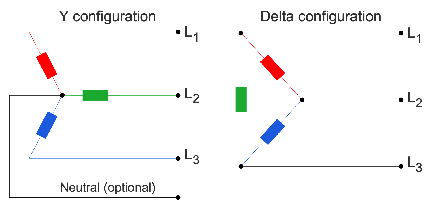
Example 3. Circuit Diagrams - Basic 3-Phase Configurations
The Circuit Diagrams samples you see on this page were created in ConceptDraw DIAGRAM software using the drawing tools of the Basic Circuit Diagrams Solution. These examples successfully demonstrate the solution's capabilities and the professional results you can achieve using it. An experienced user spent 5-15 minutes creating each of these samples.
Use the drawing tools of the Basic Circuit Diagrams solution to design your own Circuit Diagrams and schematics quick, easy, and effective.
All source documents are vector graphic documents. They are available for reviewing, modifying, or converting to a variety of formats (PDF file, MS PowerPoint, MS Visio, and many other graphic formats) from the ConceptDraw STORE. The Basic Circuit Diagrams Solution is available for ConceptDraw DIAGRAM users.

