Circuit Symbols
Electricity and electronics are ones of the most advanced and critical branches in the modern world. The meshes, which supply a seamless and uninterrupted flow of electric currents, electronic devices and electrical equipment operate and surround us everywhere providing comfort and decent living standards.
Development of any mesh or device begins from the documentation including circuit diagrams, circuit layouts, or schematic diagrams. They are essential to correctly install and connect, and also repair electric devices and fix failures in meshes.
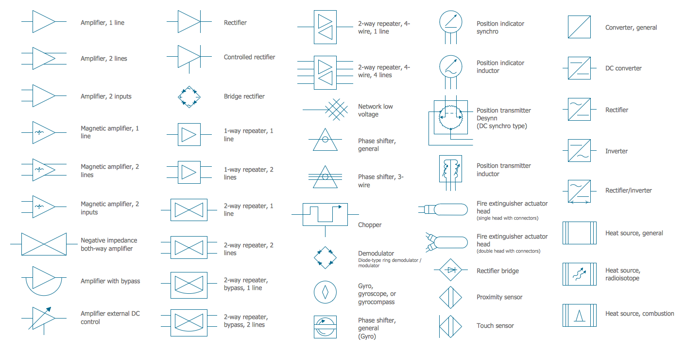
Circuit diagrams and layouts are graphical representations of electronic circuits. They are a simple, pictorial, and effective way to show the components of electrical devices, their electrical connections and interactions in a circuit, and the mechanisms of operation of electrical circuits. To show the components and connections and identify their type and position within electrical circuit diagrams, the generally accepted electrical and electronic circuit symbols are used.
The generally accepted and standardized representation of electronic symbols, signs, or pictograms allows creating of diagrams clear and understandable for all stakeholders. The lines, dots, letters, numbers, and shading define uniquely a meaning of a symbol.
The circuit symbols include symbols for switches, resistors, capacitors, diodes, inductors, transistors, amplifiers, transformers, antennas, power supplies, logic gates, and many more electronic and electrical components. Each unit has its individual function in a circuit. Through using power supply units, electrical energy is supplied to the load and devices. Switches help you to connect the circuits according to your needs, close and open the circuits. Diodes control the electron current flow from the cathode to the anode. Resistors operate to oppose the current flow in a circuit. Capacitors store electrical energy, allow flowing AC current, and block DC current. Transistors control the flow of current and voltage in the circuits and amplify or switch electronic signals and electrical power. Transformers increase and reduce AC voltages.
The components in circuits are interconnected with wires, which pass the flow of current from one part of a circuit to another. They are made with flexible materials and are shown as lines in Circuit diagrams.
Example 1. Circuit Symbols in Electrical Engineering Design
The specially developed drawing packages with pre-made fundamental forms of different circuit symbols are useful to create Circuit diagrams fast and easily. ConceptDraw DIAGRAM with Power Circuits solution is a powerful software for creating Electrical circuit diagrams, schematics, and layouts. It includes 10 libraries with a variety of electrical circuit symbols, including different kinds of design elements — windings connections, power switches, transformers, motors, starters, and many more electrical components.
- Electrical Motors
- Electric Generators
- Motor Starters
- Power Stations
- Power Switching
- Synchro Motors 3-Phase Motors
- Three Phase Transformers
- Transformers Single Line Notation
- Transmission Lines Electrical Distribution
- Windings Connections

Example 2. AC Chopper Electrical Circuit
These symbols are necessary and useful to create Circuit diagrams and Electronic drawings to professionally and visually convey information about the arrangement of components and wiring. These diagrams are an essential part of the documentation for the development, use, and repair of electrical devices and appliances.

Example 3. Electrical Circuit Design in ConceptDraw DIAGRAM
The Electrical circuit samples you see on this page were created in ConceptDraw DIAGRAM software using the drawing tools of the Power Сircuits Solution. These examples successfully demonstrate the solution's capabilities and the professional results you can achieve using it. An experienced user spent 5-10 minutes creating each of these samples.
Use the drawing tools of the Power Сircuits solution to design your own Electrical Circuit diagrams, schematics, and layouts quick, easy, and effective.
All source documents are vector graphic documents. They are available for reviewing, modifying, or converting to a variety of formats (PDF file, MS PowerPoint, MS Visio, and many other graphic formats) from the ConceptDraw STORE. The Power Сircuits Solution is available for ConceptDraw DIAGRAM users.