Electrical Diagram Symbols F.A.Q.How to Use Electrical ConceptDraw Diagram Software
Electrical circuit diagrams are a common daily tool for electricians, electrical engineers, and other technicians. It is useful and convenient because shows complex electrical systems and circuits in a simple pictorial format.
Drawing an Electrical Diagram is easy with the specialized electrical diagram drawing software ConceptDraw DIAGRAM. Depending on the type of Electrical diagram it requires variations of electrical symbols set. The symbols located in the libraries of Electrical Engineering Solution — electrical diagram symbols from the Industrial Engineering Area at the ConceptDraw Solution Park cover all needs in electrical drawing tools.
Example 1. Electrical Diagram — Lamp
Common Symbols for Basic Components
Drawing electrical circuit diagrams, you need to represent various electrical and electronic devices (such as batteries, wires, resistors, transistors, and many others) as pictograms called electrical symbols. Traditionally these symbols may vary from country to country, but currently, they are standardized internationally to a large extent. Therefore each technician gains a correct understanding of the electrical schematic and can operate with it with no effort and ambiguity.
Electrical Engineering Solution for ConceptDraw Solution Park includes a set of electrical engineering samples and 26 libraries with 926 electrical schematic symbols for a variety of electrical diagram applications. These tools are useful for both professionals and beginners and help in drawing Electrical diagrams and schematics in ConceptDraw DIAGRAM electrical diagram software. Each electrical pictogram and circuit symbol chart included in Electrical Engineering Solution libraries is vector and resizable without loss of quality.

Example 2. Electrical Symbols: the libraries of Electrical Diagram Symbols in ConceptDraw STORE
Resistors: Understanding Resistance
Resistance is a force that counteracts the current flow in an electrical circuit. It is calculated using Ohm’s Law and is expressed in ohms. Resistance is determined by the characteristics of the conductor through which the electricity is flowing, in particular, by its shape, length, material, and temperature. Resistance increases with temperature. The higher resistance also corresponds to a longer conductor. At the same time, the conductors with a large cross-sectional area have low resistance and electricity flows more readily through them. Also, electricity flows more readily through metals because their resistance is lower. Resistance is low in circuits carrying large currents, and conversely, higher resistance corresponds to the lower current in a circuit.
Resistors are electronic components made of materials that resist the flow of electricity in a circuit. They are used to control the flow of current, adjust current and voltage, and distribute voltage in a circuit. At the reducing current by a resistor, the surplus electrical energy is converted into heat. The main resistor types include fixed carbon-film and metal-film resistors with fixed resistance, variable resistors with changeable resistance, and potentiometers, which are variable resistors used to fine-tune voltage and current.
Resistors library from the Electrical Engineering Solution for ConceptDraw DIAGRAM electrical diagram software contains 14 electrical element symbols of resistors for drawing electronic schematics, circuit diagrams and electrical drawings.
Pic 1. Electrical Symbols: Resistors Library
Capacitors: Storing Electrical Charge
A capacitor is a device that stores electrical energy in the form of electrical charge on two metal plates separated by insulating material or dielectric. One of these plates is charged positively and another negatively. The plates are wired to two electrical connections on the surface called terminals. The charge stored during a capacitor is proportional to the electric potential between the plates. Capacitors charge and discharge quickly and provide high currents. When a capacitor is connected to a power source, the accumulation of energy is realized. At the moment of discharge, when the capacitor is disconnected from the charging source, the energy is released. This ability allows using of capacitors as energy sources in the automotive industry, electric cars, industrial electrical motors, uninterruptible power supplies, audio equipment, camera flashes, computer memory, etc.
The amount of stored energy depends on the amount of charge on the plates and the voltage across the capacitor. Once the capacitor is fully charged, it can release the energy. Due to the low internal resistance, the stored energy is often released extremely quickly, in seconds or less. This phenomenon is used in systems that generate large load spikes.
Electrical Circuits library contains 49 electrical element symbols of electrical and electronic devices, including ignitors, starters, transmitters, circuit protectors, transducers, radio and audio equipment. Use it for drawing electronic circuit diagrams and electrical schematics.
Pic 2. Electrical Symbols: Electrical Circuits Library
Inductors: Elements of Electrical Inductance
Inductance is the tendency of an electrical conductor to oppose a change in the electric current flowing through it, to store energy in a magnetic field when an electric current flows through it, and create an electromotive force or voltage in the circuit. Being a proportionality constant, inductance depends on the circuit conductor's geometry characteristics, in particular, its length and cross-section area, magnetic permeability, and nearby materials. An electronic passive component designed to add inductance to a circuit is called an inductor and consists of a coil of wire tightly wound around a solid central core in the form of a straight cylindrical rod, continuous loop, or ring.
An electric current generates a magnetic field around a conductor when flows through it. Meanwhile, the magnetic field is much stronger for the wire shaped into a coil. If the current changes, the magnetic field also changes and induces an electromotive force or voltage in the conductor, which opposes the change in current according to Lenz's law. This phenomenon is the basis for the concept of inductance. The inductor temporarily stores energy in a magnetic field and helps to handle fluctuations in an electric current running through a circuit.
Inductors library contains 41 electrical element symbols of inductor elements for drawing electronic circuit diagrams.
Pic 3. Electrical Symbols: Inductors Library
Symbols for Power Sources and Distribution
A power source is a device that delivers energy into a system. These devices include generators, thermopiles, photovoltaic cells, primary-cell batteries, and others. The power sources create electrical voltage and flow of the electrical current in a circuit.
Electric power is carried from power sources through a transmission system and distribution system to individual consumers. The electricity distribution is the final stage in the process of electricity delivery. The power distribution system connects high-voltage and medium-voltage substations to the final users.
Power Sources library contains 9 electrical element symbols of power sources, power supplies and batteries for drawing the electrical schematics and electronic circuit diagrams.
Pic 4. Electrical Symbols: Power Sources Library
Stations library for electrical diagram software ConceptDraw DIAGRAM contains 110 electrical symbols of communications equipment, generating, transmitting and receiving stations; substations; satellites; power plants for power generation and distribution and radio relay systems.
Pic 5. Electrical Symbols: Stations Library
Symbols for Conductors and Connectors
Electrical conductors are materials that have high electrical conductivity. They allow electrons to move freely and electric current flows through them with minimal or no resistance. Electrical conductors are widely used as wiring in electrical circuits. As a rule, these are metals, such as copper, aluminum, steel, platinum, silver, gold, brass, and metal alloys.
When an electrical circuit is constructed, coupling devices of different types called connectors are used to join electrical terminations, wires, cables, electronic components, printed circuit boards. They provide a reliable transmission of data, power, or signal in a circuit. Connectors also allow connecting the parts of an electrical circuit and separate electrical circuits in a large circuit.
Semiconductors library contains 22 electrical symbols of rectifiers, diodes, charge transfer and electronic conduction devices, switches, cathodes, transistors, thyristors, and transceivers for semiconductor (SIS) design using professional program for wiring diagrams.
Pic 6. Electrical Symbols: Semiconductors Library
Terminals and Connectors library contains 43 electrical element symbols of terminals, connectors, plugs, polarized connectors, jacks, coaxial cables, and conductors. Use it for drawing wiring diagrams, electrical layouts, electronic schematics, and circuit diagrams.
Pic 7. Electrical Symbols: Terminals and Connectors Library
Transmission Paths library contains 43 electrical symbols of power transmission paths, electronic circuits, bus connectors and elbows, terminals, junctions, and concentrators. Use it to annotate electrical symbols and electrical diagrams, electronic schematics and circuit diagrams in wiring diagram software ConceptDraw DIAGRAM.
Pic 8. Electrical Symbols: Transmission Paths Library
Symbols for Control Devices
Control devices are used to regulate and manage the operation of an electrical circuit. These devices allow turning on and off the current flow in an electrical circuit, controlling the current flow in certain parts of a circuit or energy output from a circuit. These include switches, relays, solenoids, thermostats, time clocks, and other control devices. Control devices of different shapes and sizes are applied everywhere that electrical or electronic circuits are used.
Switches and Relays Symbols
Switches are electrical components used to connect or disconnect the conducting path in an electrical circuit, interrupt the electric current, or direct it from one conductor to another. When a pair of contacts in a switch is touching, current flows between them. The separation of the contacts interrupts the current flow. Electrical switches come in a variety of types, shapes, sizes, and styles. A common use is control of lighting.
One of the common types of switches is a relay. It is an electrically operated switch that opens or closes the circuit by receiving electrical signals from outside sources. Different types of relays have different uses.
Switches and Relays library contains 58 electrical symbols of electrical contacts, switches, relays, circuit breakers, selectors, connectors, disconnect devices, switching circuits, current regulators, and thermostats for electrical devices.
Pic 9. Electrical Symbols: Switches and Relays Library
Specialized Symbols in Electrical Diagrams
Electrical Engineering Solution for electrical circuit diagram maker ConceptDraw DIAGRAM software includes a lot of specialized electrical symbols making drawing Electrical diagrams and schematics a simple and engaging process. Each circuit symbol chart is internationally standardized, vector, and easy to drag and drop from the solution libraries.
Analog and Digital Logic library contains 40 electrical element symbols of logic (threshold) gates, bistable current switches, current controllers, regulators, electrical generators, and amplifiers. Use it for drawing the digital and analog functions in electronic circuit diagrams and electrical schematics.
Pic 10. Electrical Symbols: Analog and Digital Logic Library
Composite Assemblies library contains 44 electrical element symbols of transmitters (electronic amplifiers, repeaters), static devices (rectifiers), phase shift circuits, gyroscopes, and gyrators. Each included circuit symbol chart is useful for designing electronic circuit diagrams and electrical schematics.
Pic 11. Electrical Symbols: Composite Assemblies Library
Delay Elements library contains 12 electrical element symbols of delay elements for drawing electrical schematics and electronic circuit diagrams.
Pic 12. Electrical Symbols: Delay Elements Library
Electron Tubes library contains 36 electrical element symbols of electron tubes. Use it for drawing electrical schematics and electronic circuit diagrams.
Pic 13. Electrical Symbols: Electron Tubes Library
IGFET library contains 18 electrical element symbols of IGFET (insulated-gate field-effect transistor) elements for drawing electronic circuit diagrams using wiring diagram creator.
Pic 14. Electrical Symbols: IGFET Library
Integrated Circuit library contains 43 components for integrated circuit design, including transducers, rotary devices, converters, registers, analog switches, counters, registers, decoders, and multiplex transmitters.
Pic 15. Electrical Symbols: Integrated Circuit Library
Lamps, Acoustics, Readouts library contains 35 electrical element symbols of lamps, acoustic components, electrical measuring instruments for drawing electrical schematics and electronic circuit diagrams.
Pic 16. Electrical Symbols: Lamps, Acoustics, Readouts Library
Logic Gate Diagram library contains 17 electrical element symbols for drawing logic gate diagrams.
Pic 17. Electrical Symbols: Logic Gate Diagram Library
MOSFET library contains 18 symbols of MOSFET (metal–oxide–semiconductor field-effect transistor) elements for drawing electronic circuits diagrams.
Pic 18. Electrical Symbols: MOSFET Library
Maintenance library contains 14 electrical symbols for maintaining electrical and electronic systems, including test, feedback and reference signals; pulses; relay contacts and coils; composite and amplifier circuits.
Pic 19. Electrical Symbols: Maintenance Library
Qualifying library contains 56 qualifying symbols. Use these shapes to annotate or specify characteristics of objects in electrical drawings, electronic schematics, circuit diagrams, electromechanical drawings, and wiring diagrams, cabling layout diagrams.
Pic 20. Electrical Symbols: Qualifying Library
Rotating Equipment library contains 55 electrical symbols of rotating equipment: converters, generators, motors, rotating machines, and their parts and labels. Use it to design systems with rotating electrical equipment (i.e., motors), armatures, brushes and related mechanical devices (brakes, gearing, clutches, interlocks).
Pic 21. Electrical Symbols: Rotating Equipment Library
Semiconductor Diodes library contains 24 electrical symbols of semiconductor diodes for drawing electronic schematics and circuit diagrams.
Pic 22. Electrical Symbols: Semiconductor Diodes Library
Thermo library for ConceptDraw DIAGRAM program for wiring diagrams contains 14 electrical symbols of thermoelectric elements for drawing electrical layouts, electronic schematics, and circuit diagrams.
Pic 23. Electrical Symbols: Thermo Library
Transformers and Windings library contains 29 electrical element symbols of transformers, windings, couplers, metering devices, transductors, magnetic cores, chokes, and a variometer. Use it to design the electromechanical device schematics and electronic circuit diagrams in electrical diagram software ConceptDraw DIAGRAM.
Pic 24. Electrical Symbols: Transformers and Windings Library
Transistors library contains 30 electrical symbols of transistors drawing electronic schematics and circuit diagrams in wiring diagram software.
Pic 25. Electrical Symbols: Transistors Library
VHF UHF SHF library contains 52 electrical symbols for VHF, UHF, and SHF circuit design, including capacitance measurers, nonreciprocal devices, modulators, phase shifters, field polarization devices, and filters.
Pic 26. Electrical Symbols: VHF UHF SHF Library
Conclusion
Look at this variety of electrical diagram symbols! Any Electrical diagram of any complexity is designed with their help in mere minutes!
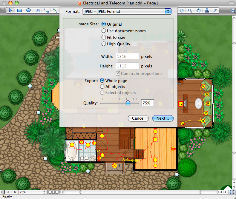
Use the Electrical Engineering Solution for ConceptDraw DIAGRAM electrical circuit diagram maker to create your own professional-looking Electrical schematics with the help of numerous pre-made vector electrical symbols in a quick, easy, and effective way; and then successfully use them in your work activity. Modify and convert your schematics to a variety of formats (PDF file, MS PowerPoint, MS Visio, and many other graphic formats) directly from the electrical schematic software.
Example 3. Electrical Diagram — 2 Bit ALU


