Diagrams Mean Nothing
Most technical blog articles have diagrams, charts, flowcharts, etc. And again, in most cases, these all don’t make any sense. I mean sense for readers. Such schemes and graphics notes are very helpful for writers to arrange their thoughts while creating an article.

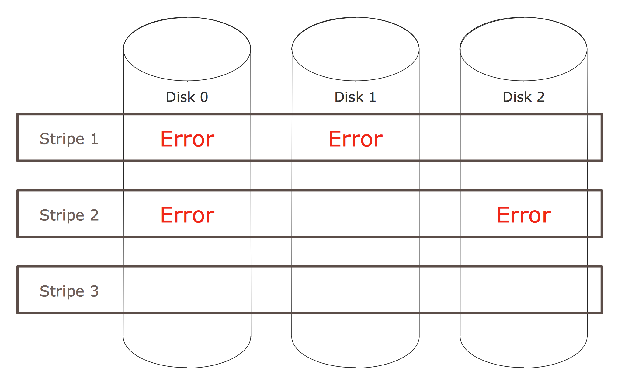
For example this illustration: if you haven't read the text, you’ll never understand what all this is about. Actually, this mess could be described just by one sentence: “The data of single stripe was damaged on several disks at the same time”.
Good Words Worth Thousand Rects
If you have enough talent and time to write a simple and clear text, you won’t need a single piece of diagram then. If you don’t, try at least to use it better.

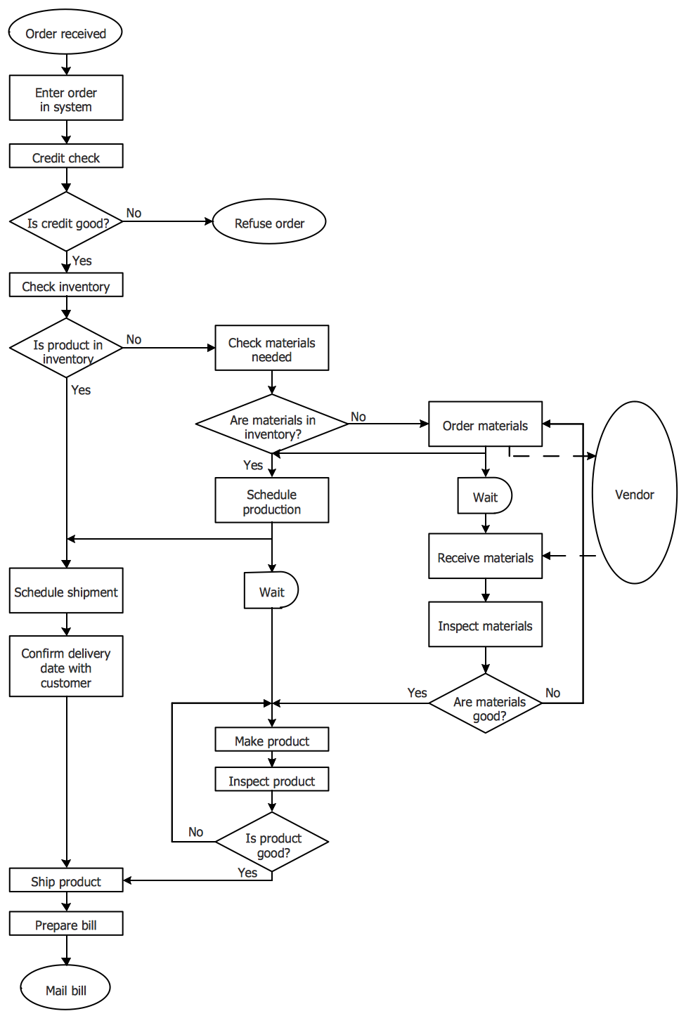
No one can neither read nor understand block diagrams. Every time someone uses it, he spends tons of words to make it clear. And at the end, you don’t remember what was in the beginning. One can easily omit block diagrams by describing a few critical points of the flow.
Use complex and abstract schemes when you are 100% sure your readers know the base and conventions. If so, then diagrams and charts become meaningful and you can use their strength at full capacity. Here we dive a bit into some of the key points to improve your diagrams.
First is a Second Dimension
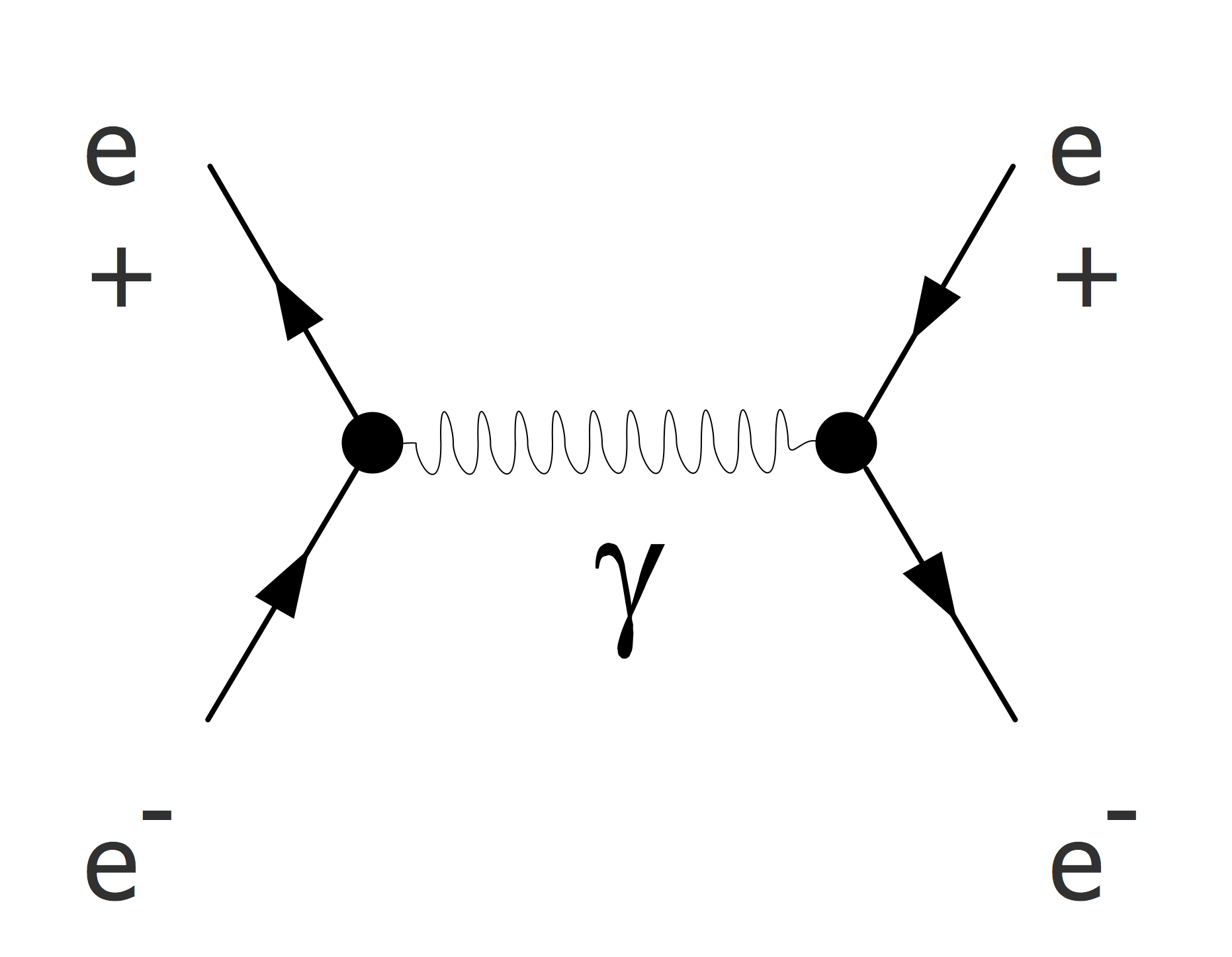
Maybe Feynman Diagrams are most extensive and dense in the sense of represented information and knowledge.

Actually these diagrams describe four dimensions. By the horizontal axis here’s time and all of our 3D world is represented in the vertical axis. And it remains true in reverse directions, so it can be read back in time too (and it does). Hence Feynman Diagrams reveal a huge amount of information in a very elegant and ascetic manner. Each symbol, element, and shape has its particular meaning.
And last but not least is using of text. Text appears as much as it needs to mark key points. No legend, no coordinates, no terms. This is the first sign your diagram is on its way to being perfect.
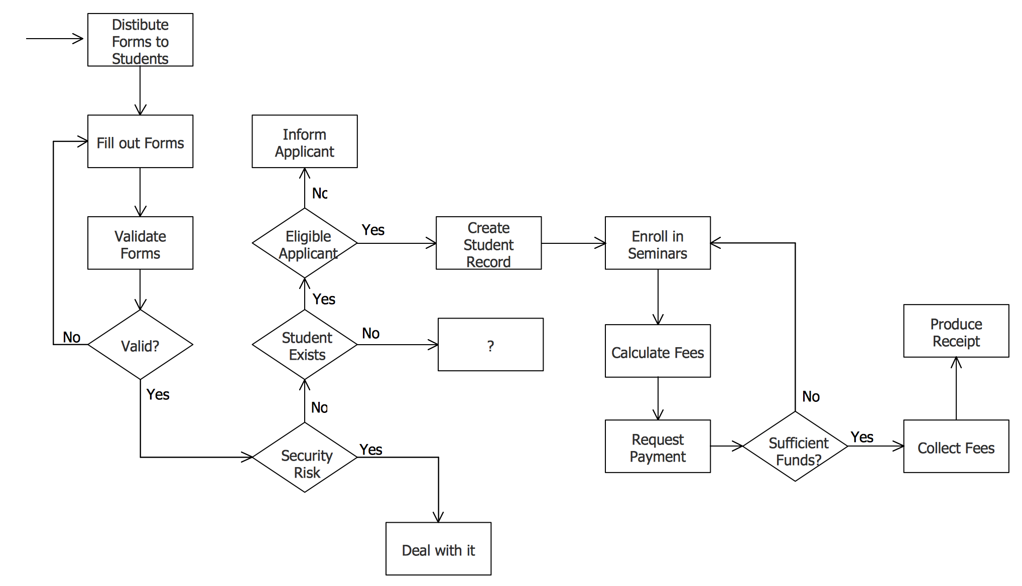
Flowcharts use both directions as well. But in contrast with Feynman Diagrams, Flowcharts use inconsistent way: in some part time is on the horizontal axis, in some not.

Much easier is to read the outline itself instead of the chart representing it. So, don’t hesitate to just write down a list. The advantage of a list is that it has one dimension hence it would be much clearer (if it’s not too long).
Second is a Third Dimension
A flat image has its own z-depth. It could be emulated by shadows, focus-depth, blur, color palette, or using gradients.

Here we have an impression of a 3D picture, but it does not have any additional value. It’s just decoration. And as it normally happens with decoration, the graph has lost a lot of its readability. Never place text on a gradient. Of course, if you want, it could be read easily.
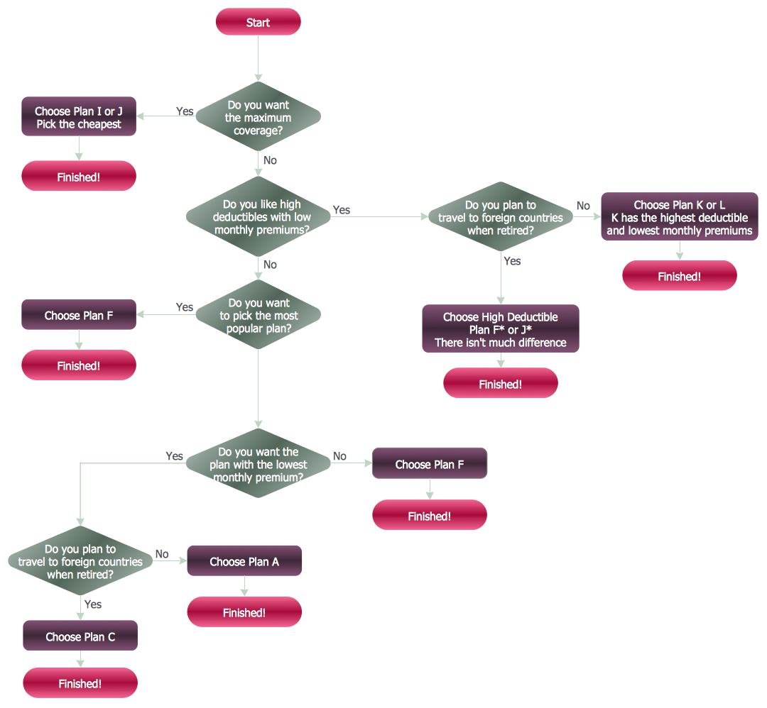
Third dimension helps us to layer information. Color is the most significant tool for this purpose. We can filter parts of the diagram by their colors in a few moments:

Note how fast you can find the endings of each chain colored in yellow. This schema may be a bit overcolored and colors are too saturated. Anyway, color layering works well.
We’ll discuss coloring in more detail in the next articles. Here are just a few points so far:
- Use the ConceptDraw DIAGRAM software and its powerful Flowcharts solution to design a Flowchart of any type without effort.
- Use colors from the palette.
- Using 3-4 colors maximally is recommended.
- Take into attention that as more colors, as less their saturation.
NINE RELATED HOW TO's:
When describing any computer network, we imagine a set of devices and nodes, arranged in some way. Talking about network structures, we should distinguish physical and logical network topologies, as physical topology is about devices location and logical topology illustrates data flow. In the same time, they do not have to match, and some devices, such as repeaters, may have a physical star layout, but a bus logical topology.
There are two main types of computer network topologies: Physical topology that show the physical organization of a network - equipment and types of connections. Star network topology involves a set of devices that is connected to a single hub (router). Ring network topology means that, devices connected according this topology have two connections, connecting with nearby devices to make a loop. Bus network topology is the topology presented at the current diagram. It is similar to a ring topology. The difference is that data moves up and down a linear connection, copying itself where network equipment works as bus-stations along the way. This network topology can be used for small network, or when adding an extra device into a network.
Picture: Network Topologies
Related Solution:
ConceptDraw DIAGRAM is a Wireless Network Drawing Mac OS software.
Picture: Wireless Networking for Mac
Related Solution:
But it never matters which hotel plan you want to illustrate in a way of a floor plan, you can always do it with ConceptDraw DIAGRAM especially it can be simple to do having the “Floor Plans” solution, which can be downloaded from the Building Plans area of ConceptDraw Solution Park.
Picture: Mini Hotel Floor Plan. Floor Plan Examples
Related Solution:
Pyramid diagrams help you visualize information as a triangle divided into horizontal slices. Labelled slices represent a hierarchy. Pyramids are used in marketing presentations to show and analyze hierarchy levels.
3D triangular diagram of DIKW pyramid has 6 levels: measurement, facts, data, information, knowledge, wisdom.
The data component include different scattered signs or symbols which are merely useless until these random objective facts are somehow processed. Data is a resource which has to be manipulated or rearranged to get useful. Information can be extracted from a pile of data, it also can be mined from different data storages.
Picture: Pyramid Diagram
Related Solutions:
ConceptDraw DIAGRAM diagramming and vector drawing software offers the unique Business Process Mapping Solution from the Business Processes Area of ConceptDraw Solution Park. Powerful drawing tools of this solution make it effective Business Process Mapping software and help easy design professional looking business process diagrams and flowcharts.
Picture: Process Mapping
Related Solution:
This method of problem analysis is widely used in IT, manufacture industries and chemical engineering. If you want to take a fresh look on your problem, you can draw a fishbone diagram with ConceptDraw DIAGRAM software, which supports both MAC OS and Windows. You can see and download fishbone diagram samples and templates in ConceptDraw Solution Park.
This Fishbone (Ishikawa) diagram can be applied as template for performing the cause and effect analysis of a service industry problems. It can help to determine factors causing problems. Causes in this diagram are categorized according to the 4S’s principle that means Surroundings, Suppliers, Systems and Skills. Grouping causes allows to reveal main interactions between different events. This diagram was made using ConceptDraw Fishbone diagrams solution. It can help to reveal the causes effected a complicated issue. Of course it can be used together with other methods of approaching to the problem solving.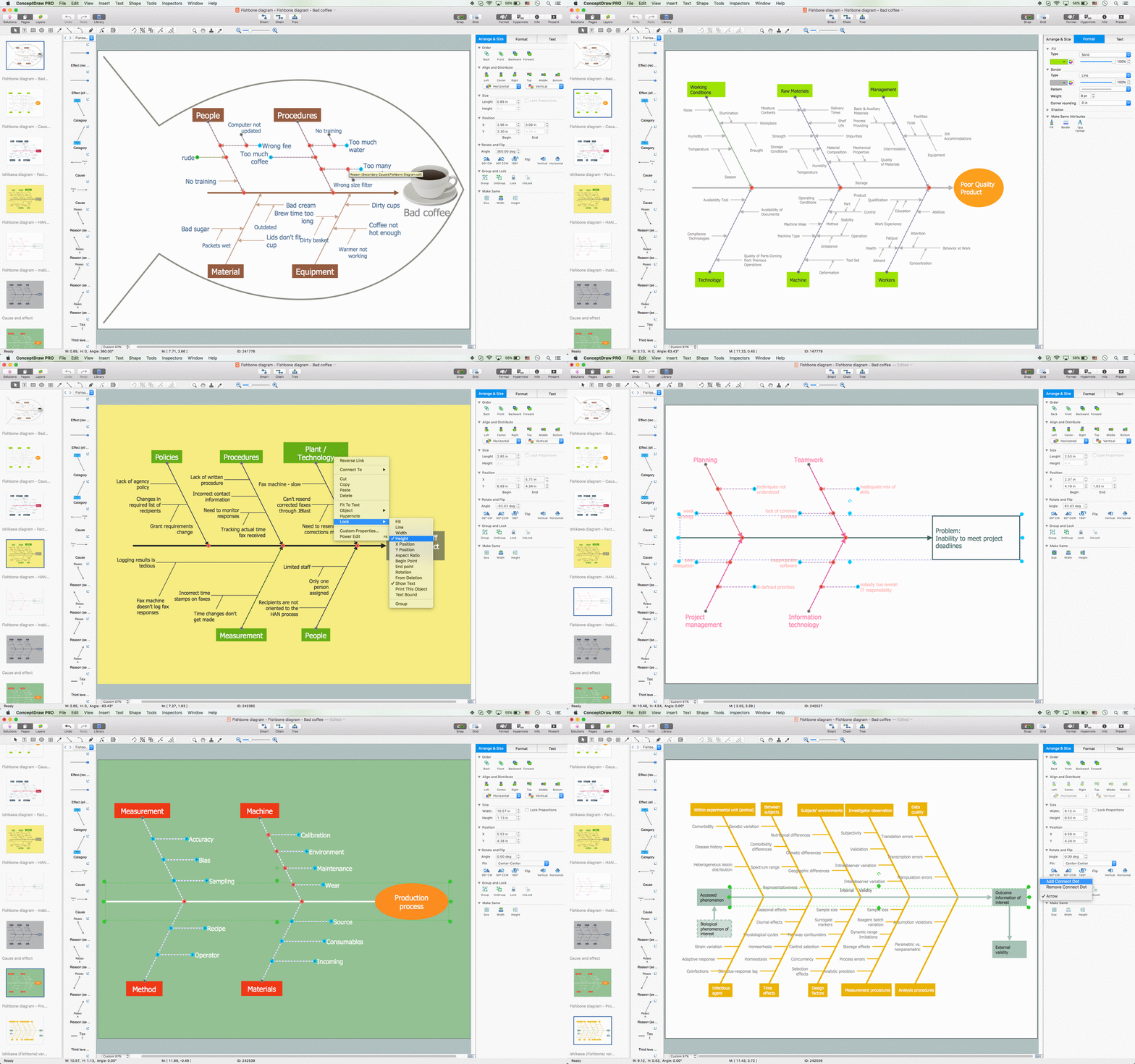
Picture: Draw Fishbone Diagram on MAC Software
Related Solution:
The Onion Diagram is a type of circular diagram which consists of the core circle and concentric circles that look like the cross sections of onion. The key value of the Onion Diagram is to visually demonstrate the relationships that lead to a successful final product or deliverable.
Design of Onion Diagrams and Stakeholder Onions Diagrams is a complex process, but ConceptDraw DIAGRAM diagramming and vector drawing software makes it easier thanks to the Stakeholder Onion Diagrams Solution from the Management Area of ConceptDraw Solution Park, and the set of included libraries and Onion Diagram templates.
Picture: Onion Diagram Templates
Related Solution:
The ConceptDraw Flowchart component includes a set of samples and templates. This geathered as flowchart maker toolbox which focused on drawing flowcharts of any industry standards.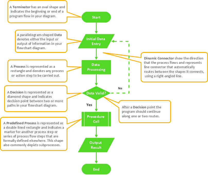
Picture: Flowchart Components
Related Solution:
Venn diagrams are illustrations used in the branch of mathematics known as set theory.
Use ConceptDraw DIAGRAM to quick and easy design your own Venn Diagram of any complexity.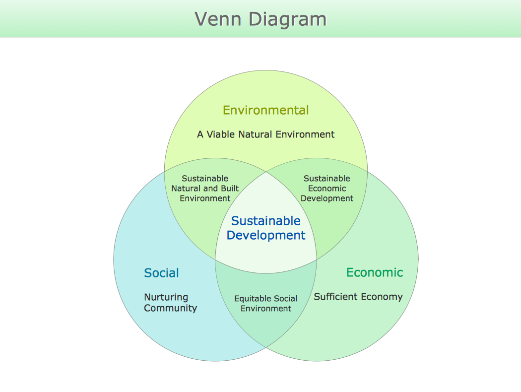
Picture: Venn Diagram
Related Solution: