Electrical Symbols
Circuit layouts, Schematic diagrams, and Electronic schematics are simple and effective ways to show the position of electrical components and their connections in electrical circuits and systems. These types of diagrams are created by using special graphical symbols - electrical and electronic symbols. These are symbols and pictograms that represent electrical and electronic components, devices, or functions and are used to develop Schematic diagrams and Circuit diagrams. The electronic symbols depict batteries, resistors, transistors, amplifiers, converters, switches, transformers, capacitors, inductors, diodes, logic gates, electrodes, batteries, wires, and many other electronic components. The electronic symbols are standardized internationally with some minor differences for various countries or engineering disciplines. This gives clearness of Electronic circuits and Electronic schematics to everyone.
The components of a circuit depict electrical and electronic devices using electrical symbols. They are connected with drawing lines representing the wires that electrically connect the circuit components one to another. Arrows are used to indicate the direction of current flow around a circuit or through a component.
The electrical symbols help to simplify drafting and understanding the electrical schematics. Having a set of standard electrical symbols you can depict a complex electrical circuit as a simple graphical schematic and show the arrangement of components in a visual view. Due to the standardized symbols, the ready electrical schematics are easily read by electrical specialists and other stakeholders. The actual physical connections, the layout of the electrical and electronic devices, and the principles of work are understandable in minutes. Electrical diagrams help electricians easily understand the wiring to install electrical equipment. They are also necessary to find the problem, repair electrical devices and eliminate troubleshooting.
Example 1. Digital Circuit Design Using Electrical Symbols
Creating Electrical diagrams is easy when you have a collection of pre-made electrical symbols at hand. The Digital Electronics solution for the ConceptDraw DIAGRAM software contains a collection of libraries with a large variety of pre-made electrical symbols useful for both professionals and beginners. These are the design elements — flip flop symbols, integrated circuits and electrical symbols, electronic logic symbols, logic gates, and many more. The electronic graphical symbols are offered in libraries with their names and are easy to use. They help to create complex and simple Electrical schematics, Electrical drawings, and Circuit diagrams in minutes.

Example 2. Digital Electronics Libraries
Digital Electronics solution also includes a collection of samples. All samples are useful to be used as a basis for your own diagrams. You can customize them according to your needs without any effort. Moreover, you can easily communicate with your team. You can work with one document, share it by e-mail directly from the application and use export capabilities to various formats.

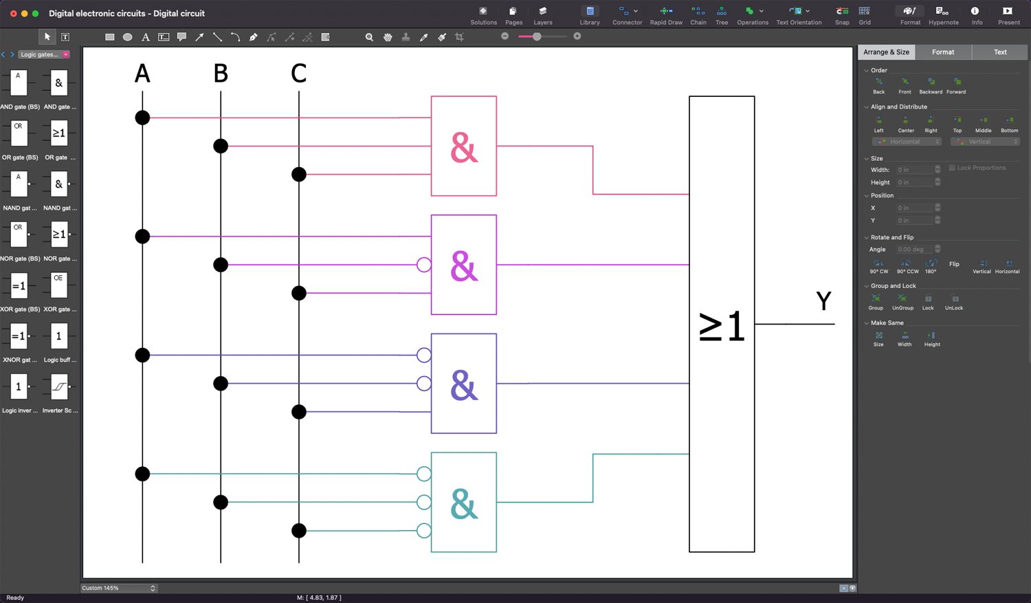
Example 3. Four Bit Majority Circuit
The samples you see on this page were created in ConceptDraw DIAGRAM software using the drawing tools of the Digital Electronics Solution. These examples successfully demonstrate solution's capabilities and the professional results you can achieve using it. An experienced user spent 5-10 minutes creating each of these samples.
Use the drawing tools of the Digital Electronics solution to design your own Digital Electronics Infographics quick, easy, and effectively.
All source documents are vector graphic documents. They are available for reviewing, modifying, or converting to a variety of formats (PDF file, MS PowerPoint, MS Visio, and many other graphic formats) from the ConceptDraw STORE. The Digital Electronics Solution is available for ConceptDraw DIAGRAM users.