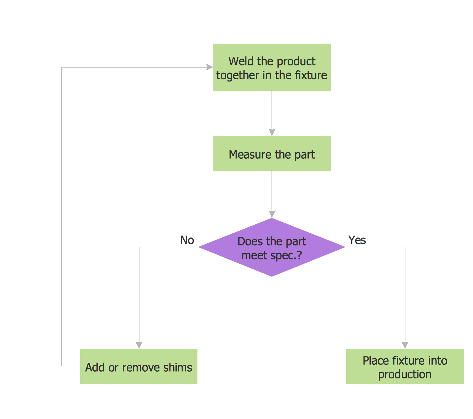
Flow Chart Drawing
Usually the flow chart drawing is a quite complex and labor-intensive process, so it would be nice to have convenient drawing software. ConceptDraw DIAGRAM extended with Flowcharts Solution from the "Diagrams" Area of ConceptDraw Solution Park is ideal flow chart drawing software for engineers, developers, designers, and more other people.

Example 1. Flow Chart Drawing
For Flow Chart drawing are used rectangular boxes which represent steps of the processes, ovals which lets to show starting or ending points, arrows - for illustrating order of the steps, and some other symbols.
Flowcharts Solution offers 2 libraries - Flowchart and Flowcharts Rapid Draw with collection of shapes for easy drawing Flow Charts. This solution also includes large collection of flow chart samples, and predesigned template for quick start. Use ConceptDraw STORE to receive access to all these tools.
Example 2. Example Flow Chart
The following features make ConceptDraw DIAGRAM the best Flow Chart drawing software free:
- You don't need to be an artist to draw professional looking diagrams in a few minutes.
- Large quantity of ready-to-use vector objects makes your drawing diagrams quick and easy.
- Great number of predesigned templates and samples give you the good start for your own diagrams.
- ConceptDraw DIAGRAM provides you the possibility to use the grid, rules and guides. You can easily rotate, group, align, arrange the objects, use different fonts and colors to make your diagram exceptionally looking.
- All ConceptDraw DIAGRAM documents are vector graphic files and are available for reviewing, modifying, and converting to a variety of formats: image, HTML, PDF file, MS PowerPoint Presentation, Adobe Flash, MS Visio.
- Using ConceptDraw STORE you can navigate through ConceptDraw Solution Park, managing downloads and updates. You can access libraries, templates and samples directly from the ConceptDraw STORE.
- If you have any questions, our free of charge support is always ready to come to your aid.


