Home Remodeling Software. Home Plan Examples
If you want to rebuild, replan the house, flat or any other building, you just need to create a plan. If you want change something in the design of your home, rearrange the furniture, interior objects, you also need a plan, because it’s convenient to see on the plan the future result and then start its implementation. In all these cases, you just need a ConceptDraw DIAGRAM that allows you to design professional looking Home Plans quick and easy.
ConceptDraw DIAGRAM diagramming and vector drawing software offers the Floor Plans Solution from the Building Plans area of ConceptDraw Solution Park for creating professional Home Plans.

Sample 1. Home Remodeling Software
Using the pre-designed stencils from the libraries of the Floor Plans Solution for ConceptDraw DIAGRAM you can draw your own professional Home Plans simply and quick.

Sample 2. Home Remodeling
This sample was created in ConceptDraw DIAGRAM diagramming and vector drawing software using the Floor Plans Solution from the Building Plans area of ConceptDraw Solution Park.
Floor Plans Solution contains 15 of home related symbols libraries:
- Appliances
- Annotations
- Building Core
- Bathroom
- Bedroom
- Cabinets & Bookcases
- Doors
- Dimensioning
- Furniture
- Kitchen and Dining Room
- Sunrooms
- Sofas and Chairs
- Tables
- Walls Shell and Structure
- Windows

Sample 3. Floor Plans Solution
The following features make ConceptDraw DIAGRAM the best Home Remodeling Software :
- You don't need to be an artist to draw professional looking Home Remodel in a few minutes.
- A large collection of home related symbol libraries makes your drawing home remodel quick and easy.
You get thousands of ready-made objects for everything from furniture to bathroom and kitchen fixtures. If you're doing a more technical remodel, you'll even find wiring and plumbing symbols.
- Great number of predesigned templates and samples give you the good start for your own home plan.
- ConceptDraw DIAGRAM provides you the possibility to use the grid, rules and guides. You can easily rotate, group, align, arrange the objects, use different fonts and colors to make your home plan exceptionally looking.
ConceptDraw DIAGRAM includes beautiful textures for flooring, countertops, and more.
- All ConceptDraw DIAGRAM documents are vector graphic files and are available for reviewing, modifying, and converting to a variety of formats: image, HTML, PDF file, MS PowerPoint Presentation, Adobe Flash, MS Visio.
- Using ConceptDraw STORE you can navigate through ConceptDraw Solution Park, managing downloads and updates. You can access libraries, templates and samples directly from the ConceptDraw STORE.
- If you have any questions, our free of charge support is always ready to come to your aid.
Interior Design:
TEN RELATED HOW TO's:
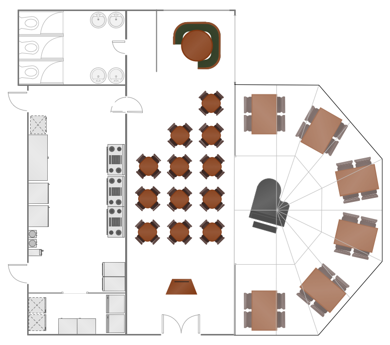
Developing Restaurant Layouts is very important and responsible moment in restaurant construction and designing. Now it's very simple and fast process thanks to the Cafe and Restaurant Floor Plans solution from the Building Plans area of ConceptDraw Solution Park.
Picture: Restaurant Layouts
Related Solution:
All these bar chart templates are included in the Bar Graphs solution.
You can quickly rework these bar graph templates into your own charts by simply changing displayed data, title and legend texts.
Picture: Bar Chart Template for Word
Related Solution:
ConceptDraw DIAGRAM extended with School and Training Plans Solution from the Building Plans Area is a powerful Classroom Seating Chart Maker.
Picture: Classroom Seating Chart Maker
Related Solution:
Designing a floor plan or a home plan using special software may sound quite complicated. There are many tools to create such plan, but it would be useful for a beginner to watch some tips on how to create home plan with examples or even templates. ConceptDraw Solution Park provides dozens of floor plans examples, templates and libraries with vector stencils.
This small private apartment floor plan is created using ConceptDraw Building Plans solution. It provides the 15 object libraries that include more than 600 vector objects along with the set of templates for drawing different floor plans. The given sample represents the individual apartment's plan in details. It shows the layout of rooms, the furniture and sanitary engineering location and even possible location of houseplants. The legend on the right side of the drawing will guide people through the location of the apartment.
Picture: How To Create Home Plan with Examples
Related Solution:
The Building Plans are very useful and even necessary for architects, builders, designers and simple for those who want to build the home, office, flat or anyone other building. They are also convenient for those who want to design or redesign the home, flat, room, etc.
Picture: Building Plan Software. Building Plan Examples
Related Solution:
The critical importance of house electrical plans. 🔸 Learn how to create efficient electrical layouts using the ConceptDraw DIAGRAM app. Enhance ✔️ safety, ✔️ functionality, and ✔️ compliance with electrical codes in your home projects with our comprehensive guide
Picture:
Importance of House Electrical Plans.
How to Create Electrical Layouts
with ConceptDraw DIAGRAM App
Related Solution:
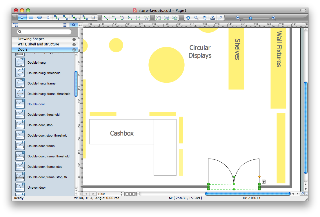
A layout is a way that furniture is arranged in some place. It’s not difficult to develop a store layout using software with tons of templates and libraries with vector shapes of furniture, doors, walls etc. Create a plan in five minutes and have more time to implement it.
Designing the floor plan for a new store is very important step for a small business. Well thought out and well-done floor plan is the foundation of the store layout. It should provide a basis through which to make out and organize everything else. Sometimes a small stores have a small floor space, so well thought out arrangement of furniture and commercial equipment is crucial to the success of the business. By using the ConceptDraw Floor Plans solution you can make a floor plan for your store quickly and effortlessly.
Picture: Store Layout Software
Related Solution:
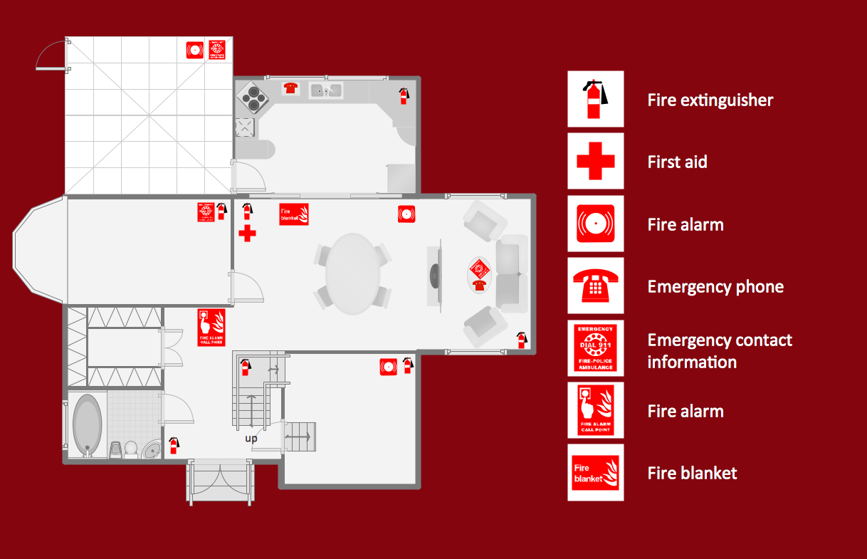
ConceptDraw DIAGRAM diagramming and vector drawing software is the best choice for making professional looking Emergency Plan template, examples and samples. ConceptDraw DIAGRAM provides Fire and Emergency Plans solution from the Building Plans Area of ConceptDraw Solution Park.
Picture: Emergency Plan Template
Related Solution:


