Landscape Architecture with ConceptDraw DIAGRAM
|
The concept landscape architecture includes landscape planning, design and creation, as well as the management of resources and buildings. With reference to smaller scale projects the design stage and planning are referred to as landscape design. Accordingly, for owners of private houses the time scales and size of projects are smaller, and the section for such projects is referred to as garden design.
The specific design documentation is created independently from the scale of project, and at this stage the irreplaceable assistant for you is ConceptDraw.
Included in the project documents are:
- sketches,
- a general plan,
- working documentation.
In addition to this, included in the working documentation besides various estimates and pages are also:
- The marked drawing of a lay-out on which is shown how the building elements will be added to an
already existing structure. On this drawing all existing lines of supply such as water and gas
pipelines, as well as electricity and telephone lines must be marked out.
- The planting drawing and development plan. On the planting plan is shown how the planted area will
be laid out and how it will fit in with the other elements of the plan. On this landscape
development plan the fixed arrangement of specific plants is shown.
|
|
Drawings and plans can all be created using ConceptDraw library objects such as trees, bushes, ponds, fountains, plots, fences, garden accessories, furniture, roofs, patios, flowers, grass, plumbing, roads, junctions, entertainment, walls, windows, doors, etc.
|
|
|
By using multilayered pages, all your work can be collected together on one ConceptDraw
document. As well as this, by using layers on one drawing it is possible to show the levels
of the location dynamically, the plan of the location with lines of supply, and also the
plan with and without buildings.
To create a ConceptDraw drawing you first have to open a template from a gallery and then
all the libraries needed for your work will open automatically.
|
|
|
After opening a template you can set its parameters, such as unit of measurement, scale and
page size. Then simply drag the objects you need from the library to the document page, set
the sizes and arrange them how you want.
|
|
|
The convenience of ConceptDraw is that although you can only place available library objects on the page
of the document, you can always create an object and add it to your own library for later use.
Objects in ConceptDraw can be connected to each other or to a group. For example, if you show a water
pipe in the form of a connection between two final points, when moving these points it will
automatically be extended or shortened.
As the plan created using ConceptDraw is not a static document, it can be used not only in the work of
landscape architects and engineers, but also by landscape managers who maintain artificial landscapes
such as parks and gardens, or natural landscapes like woodlands or nature reserves. The landscape
manager or engineer can easily transfer ConceptDraw objects of landscape design directly to a document
in order to view the end result, as well as use ConceptDraw smart objects to understand their physical
influence on the environment. For example, how the shadow from an object will change depending on the
position of the sun, how the finished work will look when viewed from a different angle such as the
window of a building, what changes the addition of new objects to an existing landscape will make, or
even how much a tree will bend in a strong wind.
|
|
|
It goes without saying that a plan or drawing created using ConceptDraw can be printed or exported to a
variety of formats such as:
- HTML for use on a web page
-
PDF for printing and viewing
-
MS PowerPoint for presentations, and many more.
|

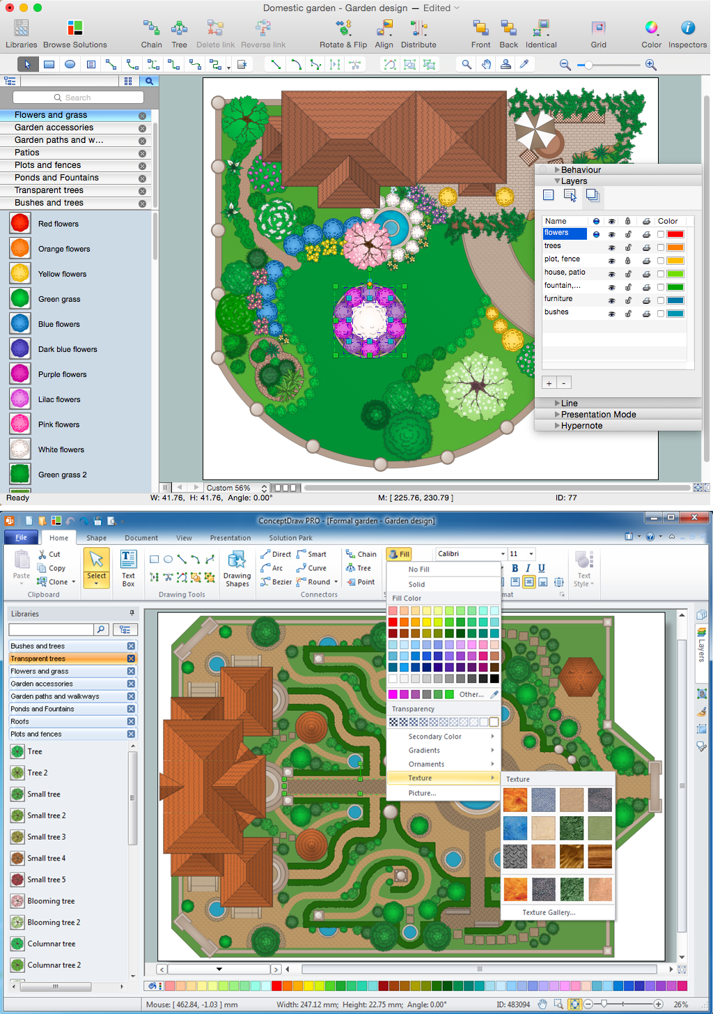
Pic. 1. Landscape Design Software for Apple OS X and Microsoft Windows
The Landscape & Garden solution for ConceptDraw DIAGRAM includes a wide collection of templates and samples to help you draw any landscape-related diagrams and schemas as quickly as possible.
Pic. 2. Landscape Architecture solution
This solution contains four libraries which are very useful for creating such plans. The Parking and Roads library contains elements for comfortable parking projection: ramps, driveway, intersections, parking lines and parking stalls.
The Site Accessories library contains useful elements with various urban objects: benches, lamp posts, site lights, drains, gates etc. You can add elements from this library to a parking plan or a street plan.
The Trees and Plants library contains various shapes of trees, tree crowns, evergreen shrubs, hedges, grass, etc.
The Vehicles 2D library contains vector shapes of cars, trucks, pickups, buses and vans. This library is useful for lane planning, parking plans, etc. You can color them with any shade you like.
It is worth mentioning that all these elements are stretchable, and you can customize them in every way you want.
The following features make ConceptDraw DIAGRAM the best Landscape Design Software:
- You don't need to be an artist to draw professional looking diagrams in a few minutes.
- Large quantity of ready-to-use vector objects makes your drawing diagrams quick and easy.
- Great number of predesigned templates and samples give you the good start for your own diagrams.
- ConceptDraw DIAGRAM provides you the possibility to use the grid, rules and guides. You can easily rotate, group, align, arrange the objects, use different fonts and colors to make your diagram exceptionally looking.
- All ConceptDraw DIAGRAM documents are vector graphic files and are available for reviewing, modifying, and converting to a variety of formats: image, HTML, PDF file, MS PowerPoint Presentation, Adobe Flash, MS Visio.
- Using ConceptDraw STORE you can navigate through ConceptDraw Solution Park, managing downloads and updates. You can access libraries, templates and samples directly from the ConceptDraw STORE.
- If you have any questions, our free of charge support is always ready to come to your aid.
TEN RELATED HOW TO's:
Interior design is an art of planning and coordinating the space in a building or on a floor to produce a charming and convenient environment for the client. You can ask professionals for help, or you can create floor plans easily with ConceptDraw DIAGRAM , using diverse libraries or altering numerous templates. You don’t need no formal training anymore to be a designer, isn’t it great?
Using a ConceptDraw DIAGRAM floor plan software makes depicting of home or office layout ideas a simple task. It does not require special skills to make detailed and scaled floor plans. Adding furniture to design interior is also a breeze. You can draw and furnish your floor plans with a floor plan software. Moreover, using software for floor planning you gain an opportunity to share your plans and high-resolution images of your designs with clients or stakeholders.
Picture:
Create Floor Plans Easily
with ConceptDraw DIAGRAM Floor Design Software
Related Solution:
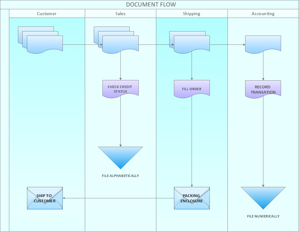
Charting Software allows you to create diagrams, charts, graphs, flowcharts, and other business graphics. ConceptDraw DIAGRAM include simple shape drawing tools, examples, templates, and symbol libraries.
Picture: Create Graphs and Charts
Related Solution:
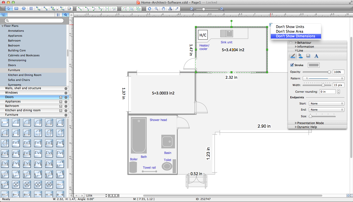
Everyone who starts the construction, repair or remodeling of the home, flat or office, is facing with a need of visualization its ideas for visual explanation how all should to be for the foreman and construction team. It is incredibly convenient to use for this professional home architect software. ConceptDraw DIAGRAM software enhanced with Floor Plans solution provides a lot of built-in drawing tools which allow you quick and easy create design plans for the home of your dreams.
Picture: Home Architect Software. Home Plan Examples
Related Solution:
The Microsoft Windows Azure platform is a highly flexible cloud-based solution with variety of services which supports not only the execution of.NET applications, but also allows developers to use programming languages like Java, PHP, Node.js, or Python.
ConceptDraw DIAGRAM diagramming and vector drawing software provides the Azure Architecture Solution from the Computer and Networks area of ConceptDraw Solution Park with a lot of useful tools which make easier: illustration of Windows Azure possibilities and features, describing Windows Azure Architecture, drawing Azure Architecture Diagrams, depicting Azure Cloud System Architecture, describing Azure management, Azure storage, documenting Azure services.
Picture: Windows Azure
Related Solution:
The blueprints are the set of drawings used by architects and builders in the process of construction of the buildings. The blueprints represent the top views on the buildings (homes, offices, etc.). They are drawn in the scale and use the special blueprint symbols and blueprints codes. Earlier the blueprints wer printed on the special paper and was blue.
It's very easy, quick and convenient to draw the professional looking blueprints in ConceptDraw DIAGRAM diagramming and vector drawing software.
Picture: Blueprint Software
Related Solution:
Aside from decorating inner spaces, which is a realm of interior design, the art of exterior design is about home facades, playgrounds and yards. To start a project, first of all, you need a site plan of the place, and a list of customers’ requirements. With special software you can do a plan of any place like parking, interchange or driveway easily.
There is one of the three libraries supplied with ConceptDraw Site Plans solution. It is designed to draw planning areas adjacent to buildings. For example parking, exit road or house territory for rest. This kind of building plans can be used for providing parking control that helps to organize traffic near residential areas. The well considered road planning will improve safety and will help to manage the number of vehicles near buildings. The ConceptDraw library "Parking and Roads" includes vector graphic images of parking spaces, lots and strips as well as street junctions, driveways and interchanges.
Picture: Interior Design. Site Plan — Design Elements
Related Solution:
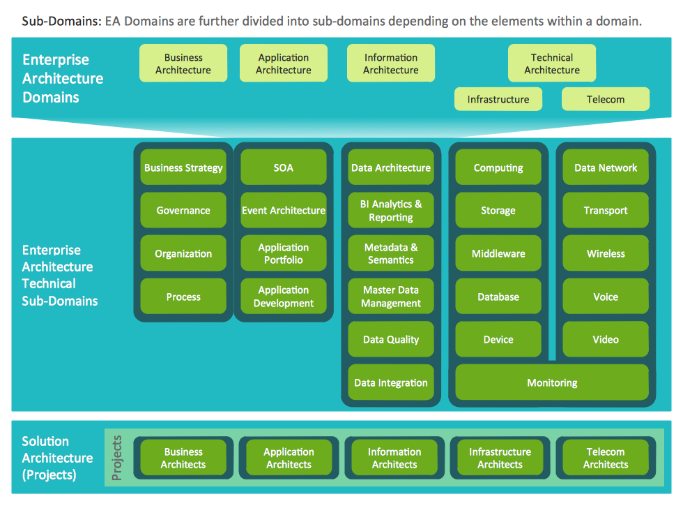
ConceptDraw DIAGRAM extended with Enterprise Architecture Diagrams Solution from the Management Area is a powerful software which provides a set of helpful tools for designing Information Technology Architecture.
Picture: Information Technology Architecture
Related Solution:
ConceptDraw DIAGRAM is the professional business graphic software for drawing diagrams and charts with great visual appeal on Mac OS X.
Picture: The Best Drawing Program for Mac
Related Solution:
What is landscape design? It's a floor plan but for an outdoor area.
Same as a floor plan, a landscape design represents visually any site using scaled dimensions.
The main purpose of landscape design is to plan the layout for an outdoor area no matter is it a personal site plan for your home or a commercial plan for business. It may also be handful when a new installation, repair or even an outdoor event is planning.
It helps to calculate time and decide which materials should be used in your project. Landscape designs perfectly gives the property owner and landscape contractor better vision for cost estimation, helping to ensure the project time and budget.
Picture: How to Draw a Landscape Design Plan
Related Solution:


