Line Graph
Looking for the line graph examples you can simply go to the Line Graphs solution of ConceptDraw STORE to get those which were previously created especially for the ConceptDraw DIAGRAM users in order to simplify their work of making such charts.
The previously Line Graphs solution contains five stencil objects that are the templates of line graphs named as “Line Graph — Relative Price Changes”, “Line Graph — Number of Airlines Departures in the Given Years”, “Line Graph — France Export of Goods and Services”, “Line Graph — Spets Walked in a Week” and “Line Graph — Percent of Students a 36 on ACT”.
You can also find some more samples of line graphs within the previously mentioned product of CS Odessa — ConceptDraw STORE. They are: “Line Graph — Circuit Efficiency Erlang B”, “Line Graph — 1918 Spanish Flu Waves”, “Veteran Point in Time Counts, 2009—2012” and “Wait Time for Treatment in Hospital Emergency Department”.
The line graph of an undirected graph G in the mathematical discipline of graph theory is another graph L(G) used for representing different adjacencies between all the edges of G. The term “line graph” is known to be originally coming from a paper by Harary & Norman, although both Whitney and Krausz used this construction before.
Other terms that are used for the line graph are known to be including the derivative, the covering graph, the conjugate, the edge-to-vertex dual, the representative graph, the edge graph, the ϑ-obrazom, the interchange graph, the derived graph and the adjoint graph.
Hassler Whitney was the one who proved that with only one exceptional case the structure of a so-called connected graph G can be recovered from its line graph completely. A lot of other properties of the line graphs are known to be following by translating the properties of the underlying graph from vertices into edges. Thus, by Whitney's theorem, the very same translation can also be done in any other direction.
All the line graphs are known to be claw-free. All the line graphs of bipartite graphs are known to be perfect. Any line graph can be characterized by nine forbidden subgraphs, being recognized in the linear time. There are many generalizations of the line graphs that have also been studied, including the line graphs of multigraphs, the line graphs of line graphs, the line graphs of weighted graphs and the line graphs of hypergraphs.
As with claw-free graphs, every connected line graph L(G) with an even number of the edges has a perfect matching. This means that in case the underlying graph G has an even number of edges, then its edges can be partitioned into the two-edge paths. All the line graphs of trees are known to be exactly the claw-free block graphs. The mentioned graphs have been used for solving a problem in an extremal graph theory.
Constructing a graph with a given number of vertices and edges whose largest tree induced as a subgraph is as small as possible. Although the line graph of a bipartite graph is perfect, it still should not be bipartite. The line graphs of the bipartite graphs form one of the key building blocks of the perfect graphs that are used in the proof of the strong perfect graph theorem.
The mentioned strong perfect graph theorem in graph theory is a forbidden graph characterization of the perfect graphs as those that have neither odd antiholes (complements of odd holes) nor odd holes (odd-length induced cycles) as it was conjectured by Claude Berge in 1961.
The rook's graphs, the line graphs of the complete bipartite graphs are all a special case of the mentioned graphs. Being characterized with only one exception by their numbers of edges, a number of shared neighbors for non-adjacent and adjacent points, and numbers of vertices the line graphs of the complete graphs can be made.
One known exceptional case is L(K4,4). It shares its parameters with the so-called Shrikhande graph. When both of the sides of the bipartition are known to be having the same number of vertices, then such graphs are known to be strongly regular.
Any Shrikhande graph in the mathematical field of graph theory is a named graph that was discovered in 1959 by S. S. Shrikhande. Being a strongly regular graph, it has 48 edges and 16 vertices, each of the vertexes having degree 6. Every single pair of nodes is known to be having exactly two other neighbors, whether the pair of nodes is disconnected or not.
Speaking more generally, a graph G is known to be a line perfect graph in case L(G) is a perfect graph. The line perfect graphs are exactly the graphs that do not contain a simple cycle of odd length greater than three. A graph is a line perfect one only in case each of its biconnected components is either of the form K4 (the so-called tetrahedron) or K1,1,n (a book of one or more than one triangles all share one common edge), or bipartite. Every line of the perfect line graph is known to be perfect itself.
No matter which of the mentioned graphs you want to create, you can make sure that the result will be simply perfect by downloading ConceptDraw DIAGRAM diagramming and drawing software getting another one called ConceptDraw STORE in order to create truly professionally looking drawings.

Example 1. Line Graph in ConceptDraw STORE
The Line Graphs solution that can be found in the ConceptDraw STORE application developed by the specialists of CS Odessa is the key to making a great looking as well as the smart looking lime graphs. Providing all the ConceptDraw DIAGRAM users with the so useful examples of the Line Graphs, it can simplify any work of creating the needed drawings making it possible to finish with them within only a few minutes.
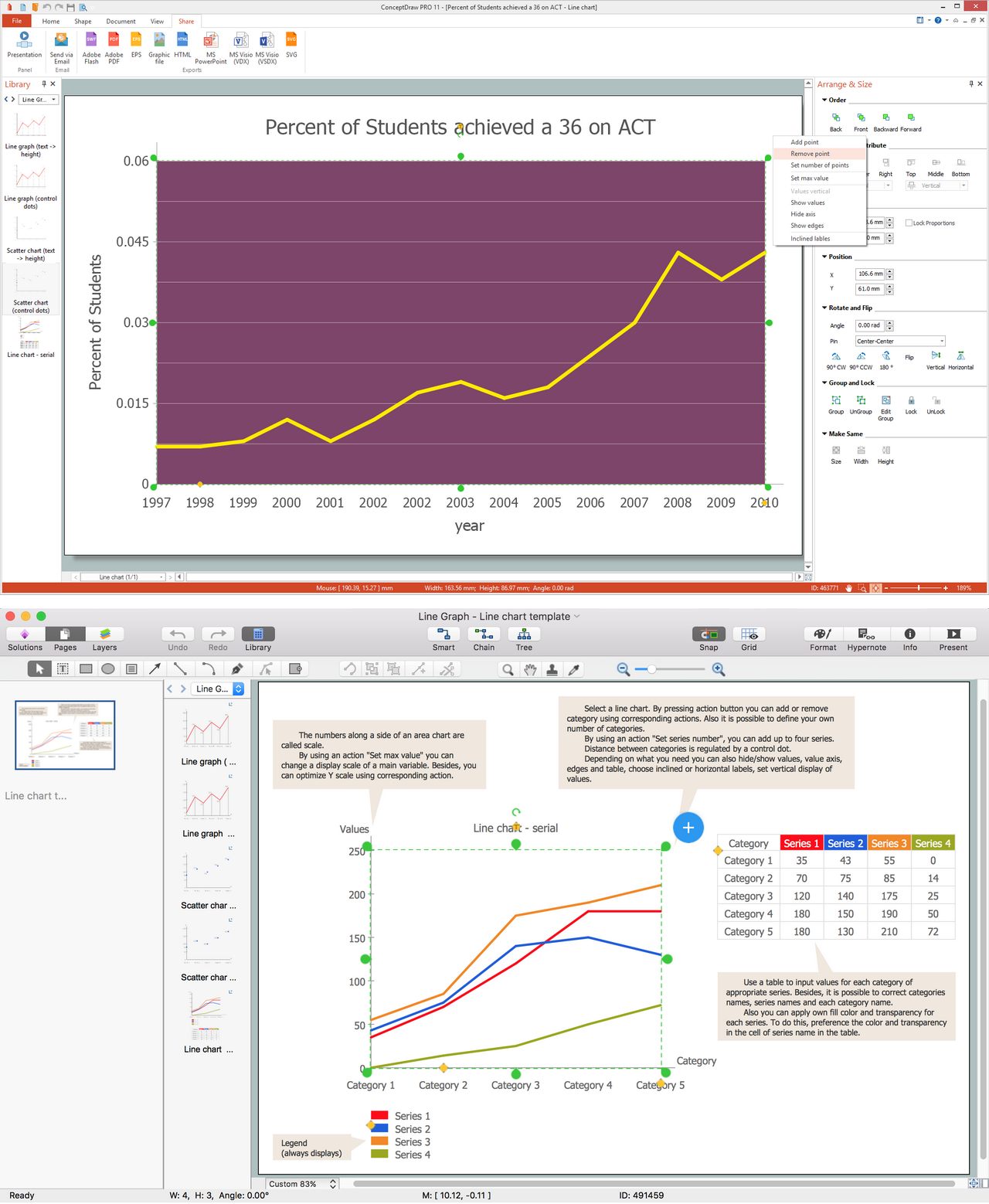
Example 2. Line Graph in ConceptDrae PRO
Having “Example 1: Line Graph — Relative Price Changes”, “Example 2: Line Graph — Number of Airlinges Departures in the Given Years”, “Example 3: Line Graph — France Export of Goods and Services”, “Example 4: Line Graph — Spets Walked in a Week”, “Example 5: Line Graph — Percent of Students a 36 on ACT”, as well as other templates, such as the “Line Graph — Circuit Efficiency Erland B”, “Line Graph — 1918 Spanish Flu Waves”, “Veteran Point in Time Counts, 2009-2012” and “Wait Time for Treatment in Hospital Emergency Department” any ConceptDraw DIAGRAM user can edit any mentioned above sample to make their own drawing.
TEN RELATED HOW TO's:
Make diagrams, charts, workflows, flowcharts, org charts, project charts easily with ConceptDraw software.
Picture: Best Program to Make Diagrams
Related Solution:
While creating flowcharts and process flow diagrams, you should use special objects to define different statements, so anyone aware of flowcharts can get your scheme right. There is a short and an extended list of basic flowchart symbols and their meaning. Basic flowchart symbols include terminator objects, rectangles for describing steps of a process, diamonds representing appearing conditions and questions and parallelograms to show incoming data.
This diagram gives a general review of the standard symbols that are used when creating flowcharts and process flow diagrams. The practice of using a set of standard flowchart symbols was admitted in order to make flowcharts and other process flow diagrams created by any person properly understandable by other people. The flowchart symbols depict different kinds of actions and phases in a process. The sequence of the actions, and the relationships between them are shown by special lines and arrows. There are a large number of flowchart symbols. Which of them can be used in the particular diagram depends on its type. For instance, some symbols used in data flow diagrams usually are not used in the process flowcharts. Business process system use exactly these flowchart symbols.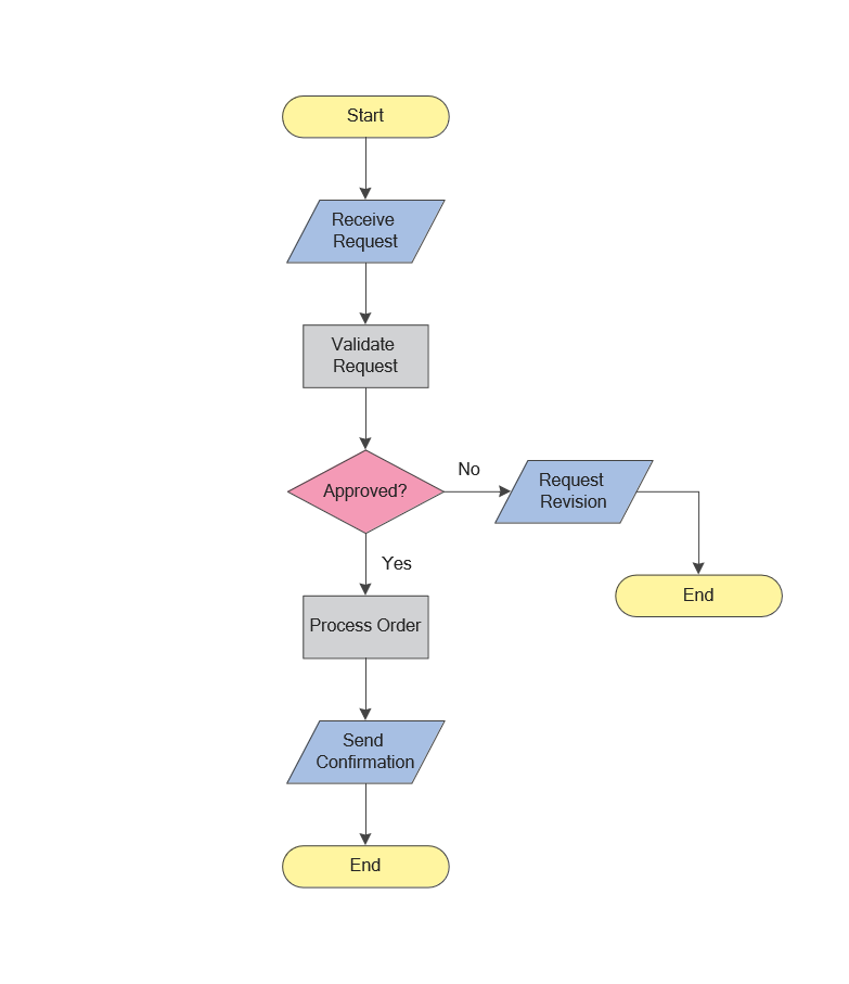
Picture: Flowchart Symbols: Meaning and Examples
Related Solution:
If you want to find a way to understand complex things in minutes, you should try to visualize data. One of the most useful tool for this is creating a flowchart, which is a diagram representing stages of some process in sequential order. There are so many possible uses of flowcharts and you can find tons of flow charts examples and predesigned templates on the Internet. Warehouse flowchart is often used for describing workflow and business process mapping. Using your imagination, you can simplify your job or daily routine with flowcharts.
Warehouse flowcharts are used to document product and information flow between sources of supply and consumers. The flowchart provides the staged guidance on how to manage each aspect of warehousing and describes such aspects as receiving of supplies; control of quality; shipment and storage and corresponding document flow. Warehouse flowchart, being actual is a good source of information. It indicates the stepwise way to complete the warehouse and inventory management process flow. Also it can be very useful for an inventory and audit procedures.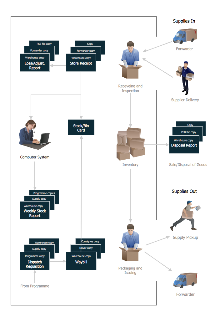
Picture: Flow Chart Example: Warehouse Flowchart
Related Solution:
Create Spatial infographics with ConceptDraw using its excellent examples of infographic maps. We hope these can inspire and teach you!
Picture: Excellent Examples of Infographic Maps
Create flowcharts, organizational charts, bar charts, line graphs, and more with ConceptDraw DIAGRAM.
Picture: Basic Diagramming
Related Solution:
Create bar graphs for visualizing economics problem solving and financial data comparison using the ConceptDraw DIAGRAM diagramming and vector drawing software extended with the Bar Graphs Solution from the Graphs and Charts area of ConceptDraw Solition Park.
Picture: Bar Diagrams for Problem Solving.Create economics and financial bar charts with Bar Graphs Solution
Related Solution:
The question how to create a column chart have a simple answer. Use ConceptDraw tips to find out how to create a column chart depicts your data the best way.
Picture: How to Create a Column Chart
Related Solution:
A flowchart is a powerful tool for examining processes. It helps improving processes a lot, as it becomes much easier to communicate between involved people, to identify potential problems and to optimize workflow. There are flowcharts of different shapes, sizes and types of flowchart vary from quite basic process flowcharts to complex program flowcharts. Nevertheless, all these diagrams use the same set of special symbols like arrows to connect blocks, parallelogram to show data receiving or rectangles for showing process steps.
Basic flowcharts are used to represent a simple process algorithm. A basic flowchart notation consists of rectangles (business processes), arrows (the flow of information, documents, etc.). The same notation is used in items such as the "decision", which allow you to do the branching. To indicate the start of the entire business process and its termination can be used the "Terminator" element. The advantages of Basic Flowchart are simplicity and clarity. With it you can quickly describe the business process steps. Creating of Basic Flowchart does not require any special knowledge, as easily understand by employees with different levels of education and IQ.
Picture: Types of Flowchart: Comprehensive Overview
Related Solution:
These libraries of vector objects depict the Site Accessories and Parking and Roads elements. They are needed to draw architectural and landscape plans that show the architectural elements around buildings: parking spaces, hiking and biking trails, drainage systems, lights, and vehicle access control elements. These libraries are included into ConcepDraw solution for Site Planning. Site Accessories and Parking, Roads libraries contain near 40 vector images that will help depict an a surrounding territory at building plans.
These libraries of vector objects depict the Site Accessories and Parking and Roads elements. They are needed to draw architectural and landscape plans that show the architectural elements around buildings: parking spaces, hiking and biking trails, drainage systems, lights, and vehicle access control elements. These libraries are included into ConcepDraw solution for Site Planning. Site Accessories and Parking, Roads libraries contain near 40 vector images that will help depict an a surrounding territory at building plans.
Picture: Building Drawing. Design Element Site Plan
Related Solution:
When trying to figure out the nature of the problems occurring within a project, there are many ways to develop such understanding. One of the most common ways to document processes for further improvement is to draw a process flowchart, which depicts the activities of the process arranged in sequential order — this is business process management. ConceptDraw DIAGRAM is business process mapping software with impressive range of productivity features for business process management and classic project management. This business process management software is helpful for many purposes from different payment processes, or manufacturing processes to chemical processes. Business process mapping flowcharts helps clarify the actual workflow of different people engaged in the same process. This samples were made with ConceptDraw DIAGRAM — business process mapping software for flowcharting and used as classic visio alternative because its briefly named "visio for mac" and for windows, this sort of software named the business process management tools.
This flowchart diagram shows a process flow of project management. The diagram that is presented here depicts the project life cycle that is basic for the most of project management methods. Breaking a project into phases allows to track it in the proper manner. Through separation on phases, the total workflow of a project is divided into some foreseeable components, thus making it easier to follow the project status. A project life cycle commonly includes: initiation, definition, design, development and implementation phases. Distinguished method to show parallel and interdependent processes, as well as project life cycle relationships. A flowchart diagram is often used as visual guide to project. For instance, it used by marketing project management software for visualizing stages of marketing activities or as project management workflow tools. Created with ConceptDraw DIAGRAM — business process mapping software which is flowcharting visio alternative or shortly its visio for mac, this sort of software platform often named the business process management tools.
Picture: Process Flowchart: A Step-by-Step Comprehensive Guide
Related Solution:
