Logic Gate Symbols
A logic gate is a basic element of a digital circuit and a device that performs logical functions. It implements a logical operation or a Boolean function and transforms a set of binary inputs into a single binary output. Logic gates use logic to determine whether an input pulse can pass to the output or not.
The logical operations are fundamental for digital circuits and widely employed in integrated circuits (ICs). The logic gates of a circuit are based on Boolean algebra, take one of two binary values 0 or 1 (false or true), and make decisions based on the input digital signals. At this, logic gates take two or more inputs but produce only one output. Boolean 1 is a closed switch, “on” state of the device, or a high voltage in an electrical circuit. And correspondingly, Boolean 0 shows an open switch, “off” state, or a low voltage. There are seven basic types of logic gates: AND, OR, XOR, NOR, NOT, NAND, and XNOR. The output result depends on the type of logic gate.
- AND logic gate produces 1 when all of the inputs are 1, otherwise the output is 0.
- OR logic gate output is 0 only when both inputs are 0 and 1 in any other combinations.
- XOR logic gate is an exclusive OR (Ex-OR) and produces output 1 if one of the inputs is 1 and 0 if both inputs are equal, both are 0 or 1.
- NOR logic gate is the negation of OR gate (NOT-OR) and produces 1 when both inputs are 0, otherwise the output is 0.
- NOT logic gate is also called an inverter because if the input is 1, the output is 0, and vice versa - if the input is 0 the output is 1.
- NAND logic gate is the negation of AND gate (NOT-AND), its output is 0 only when all inputs are 1, otherwise, the output is 1.
- XNOR logic gate is an exclusive NOR (EX-NOR), the inverse of XOR, and produces the output 1 when both inputs are 1 or 0, otherwise, the output is 0.
To implement complex Boolean functions and complex circuit designs there are also used the compound logic gates like AND-OR-Invert (AOI) and OR-AND-Invert (OAI). All possible combinations of inputs and outputs for a logic gate or circuit are defined in the Truth table.
.png)
Example 1. Logic Gate Symbols in ConceptDraw DIAGRAM
Logic gates are used in a variety of technologies. They make a choice to start or stop based on logic. Often the logic gates are combined in a variety of ways to be used in complex devices, chips, integrated circuits (ICs), electronic and electrical project circuits, microcontrollers, microprocessors. At this, the microprocessors can include 100 million logic gates. These units are embedded in gadgets, computers, laptops, tablets, smartphones, robots, satellites, memory devices, street lights, buzzers, switches, burglar alarms, and other electronic devices.
Usually, logic gates are implemented using diodes or transistors operating as electronic switches. Often these are MOSFETs (metal–oxide–semiconductor field-effect transistors), FETS, CMOS technology. Sometimes, there are used vacuum tubes, electromagnetic relays, optics, molecules, fluidics, pneumatics, mechanical elements, optical elements. Moreover, Logic circuits include registers, multiplexers, arithmetic logic units (ALUs), and other devices.
The common logic gate symbols are defined by the American National Standards Institute (ANSI), British System (BS), Deutsches Institut fur Normung (DIN), International Electrotechnical Commission (IEC), and National Electrical Manufacturers Association (NEMA).
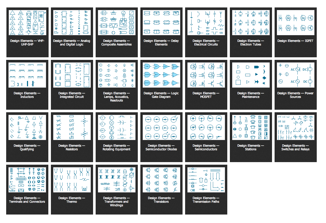
Digital Electronics solution for ConceptDraw DIAGRAM software includes a large collection of libraries with vector design elements of digital electrical symbols and logic gates of various standards, connections, electronic logic and flip flop symbols. It includes design elements — logic gates ANSI, Logic Gates BS, Logic Gates DIN, Logic Gates IEC, and Logic Gates NEMA.
 Library")
 Library")
 Library")
 Library")
 Library")
Efficient diagramming software ConceptDraw DIAGRAM helps to easier and speed up the process of designing Logic diagrams using the pre-made logic gate symbols. It is perfect for computer engineering, mechanical engineering, software development, network infrastructure, and building construction.

Example 2. 4-to-2 Encoder Using OR Gate
The samples you see on this page were created in ConceptDraw DIAGRAM software using the drawing tools of the Digital Electronics Solution. These examples successfully demonstrate solution's capabilities and the professional results you can achieve using it. An experienced user spent 5-10 minutes creating each of these samples.
Use the drawing tools of the Digital Electronics solution to design your own Digital Electronics Infographics quick, easy, and effective.
All source documents are vector graphic documents. They are available for reviewing, modifying, or converting to a variety of formats (PDF file, MS PowerPoint, MS Visio, and many other graphic formats) from the ConceptDraw STORE. The Digital Electronics Solution is available for ConceptDraw DIAGRAM users.