Network Diagramming Software for Design
IVR Network Diagrams
Design Element IVR Network Diagrams
IVR diagrams visualize the logical and physical structure of IVR systems, where computer interact with callers using of voice and dual-tone multi-frequency signaling (DTMF) keypad inputs. They are used to develop, operate and maintain the IVR systems for inbound and outbound call centers and voice mail systems.
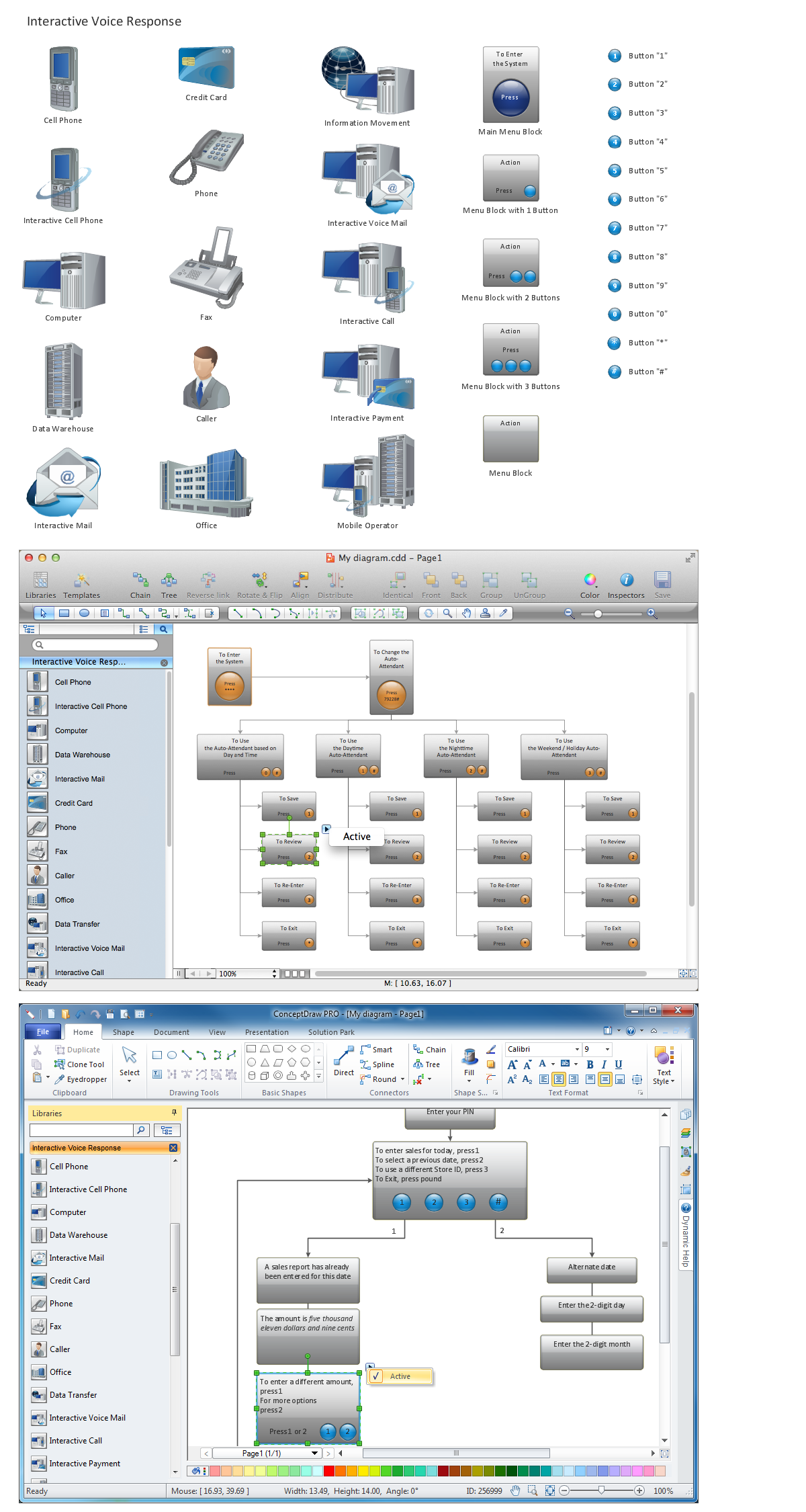
ConceptDraw has 1004 vector stencils in the 40 libraries that helps you to start using software for designing own Cisco Network Diagrams. You can use the appropriate stencils from Interactive Voice Response library with 35 objects.

Pic.1. Network Diagramming Software
Design Elements — IVR (Windows, Macintosh).
ConceptDraw solution Computer and Networks provides Interactive Voice Response library of 35 vector stencils for drawing the IVR network diagrams.
Use these libraries of design elements to visualize the logical and physical structure of IVR systems for inbound and outbound call centers and voice mail systems.
TEN RELATED HOW TO's:
Interior design is an art of planning and coordinating the space in a building or on a floor to produce a charming and convenient environment for the client. You can ask professionals for help, or you can create floor plans easily with ConceptDraw DIAGRAM , using diverse libraries or altering numerous templates. You don’t need no formal training anymore to be a designer, isn’t it great?
Using a ConceptDraw DIAGRAM floor plan software makes depicting of home or office layout ideas a simple task. It does not require special skills to make detailed and scaled floor plans. Adding furniture to design interior is also a breeze. You can draw and furnish your floor plans with a floor plan software. Moreover, using software for floor planning you gain an opportunity to share your plans and high-resolution images of your designs with clients or stakeholders.
Picture:
Create Floor Plans Easily
with ConceptDraw DIAGRAM Floor Design Software
Related Solution:
Wireless Networks solution from ConceptDraw Solution Park extends ConceptDraw DIAGRAM to help network engineers and designers efficiently illustrate wireless network mode diagrams.
Picture: Wireless Network Mode
Related Solution:
Wireless computer network diagrams help system administrators and network engineers to find out amount and type of equipment needed for each office WLAN.
Picture: Find out what amount and type of equipment is needed for your office network
Related Solution:
Database structures are usually described by ER-diagrams which represents entities as boxes with lines-connections between them. You can create any entity-relationship diagram (ERD) by means of ConceptDraw DIAGRAM using ready-to-use templates and special libraries containing all the needed symbols and shapes. Creating a model for your database from now on can take just a few minutes.
ERD (entity relationship diagram) designed to show the logical structure of databases. It intended to depict the relationships between data components (entities). ERDs are a popular tool for software engineers and architects. Using ERD they can manage the every aspect of database design. Also ERD can be used as guidelines for testing and communications before software release. This diagram represents the file reference system of the WordPress web platform. Because entity relationship diagrams have such a broad application area through the prevalence of database technology, it can be applied for a wide range of users.
Picture: Entity-Relationship Diagram (ERD) with ConceptDraw DIAGRAM
Related Solution:
Video tutorials on ConceptDraw products. Try it today!
Picture: How to Draw a Bubble Chart
Related Solution:
Even if you design a network for yourself, you still might need a network diagram software to do it in a convenient way. Your laptop, or PC, a smartphone and a router form a home area network, which might be very small, but has to fulfill all your requirements. A schematic diagram will help you to arrange all the cables and network devices in a proper way.
This wireless network diagram is made to describe the home-area network system. This diagram shows the typical wireless network organization in a private house or condominium. It consists from computers and gadgets that use wireless connections. The diagram is created using the ConceptDraw Computer Networks Diagrams solution. It is a rather common diagram that features icons depicting Wi-Fi point, router, media gadgets and periphery with connections and routes that show the flow of data.
Picture: Network Diagram Software Home Area Network
Related Solution:
A list of parameters on which networks differ is very long. A large network with a range up to 50 kilometers is called metropolitan area network (MAN), and this type of network can include several local area networks. Metropolitan networks in their turn connect into global area networks.
Here you will see a Metropolitan Area Network (MAN). This is an extensive network which occupies a large territory including a few buildings or even the whole city. The space of the MAN is bigger than LAN, but lower than WAN. MAN comprise a lot of communication equipment and delivers the Internet connection to the LANs in the city area. Computer and Networks solution for ConceptDraw DIAGRAM provides a set of libraries with ready-to-use vector objects to design various kinds of computer networks.
Picture: Metropolitan area networks (MAN). Computer and Network Examples
Related Solution:


