Network Mapper
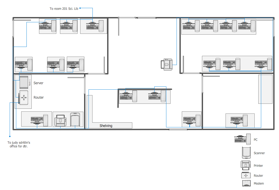
ConceptDraw DIAGRAM diagramming and vector drawing software is a powerful network mapper thanks to the extensive drawing tools of Network Layout Floor Plans Solution from the Computer and Networks Area.

Example 1. Network Mapper - Ethernet Cable Layout
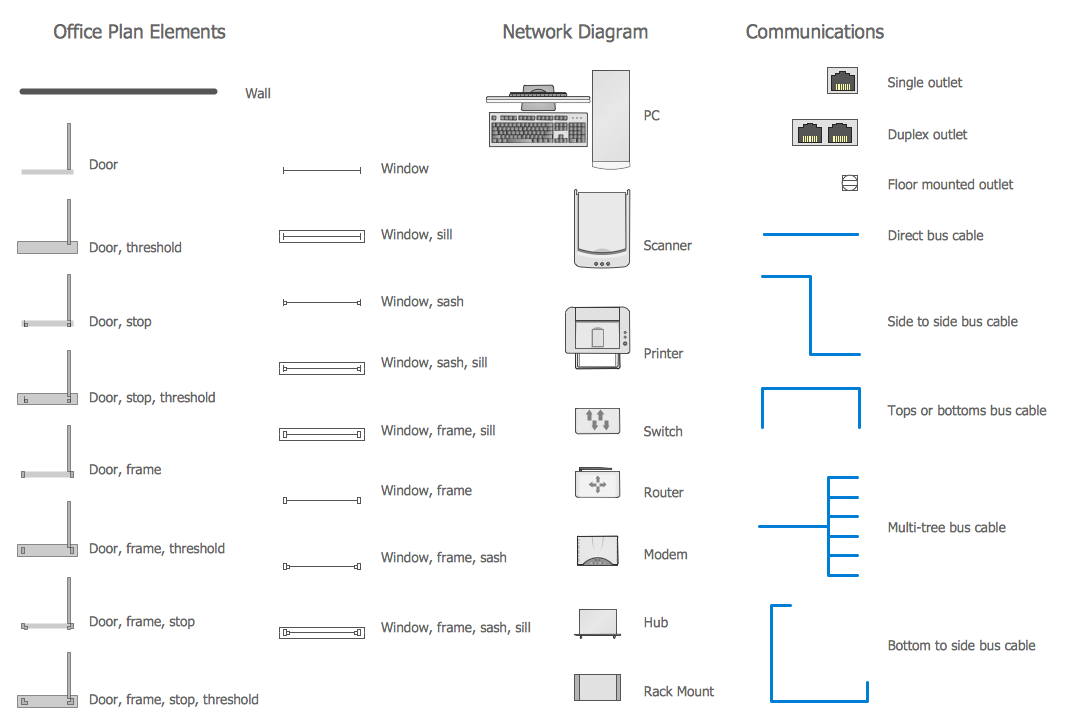
Network Communication Plan Library from the Network Layout Floor Plans Solution offers variety of home networking vector shapes which help to make ConcepDraw PRO software the best network mapper.

Example 2. Network Communication Plan Library Design Elements
The process of creating the network diagrams is now very simple. You need only drag the desired objects from the library to the document and arrange them. Add the title, callouts and colors if needed and professionally looking diagram will be ready!

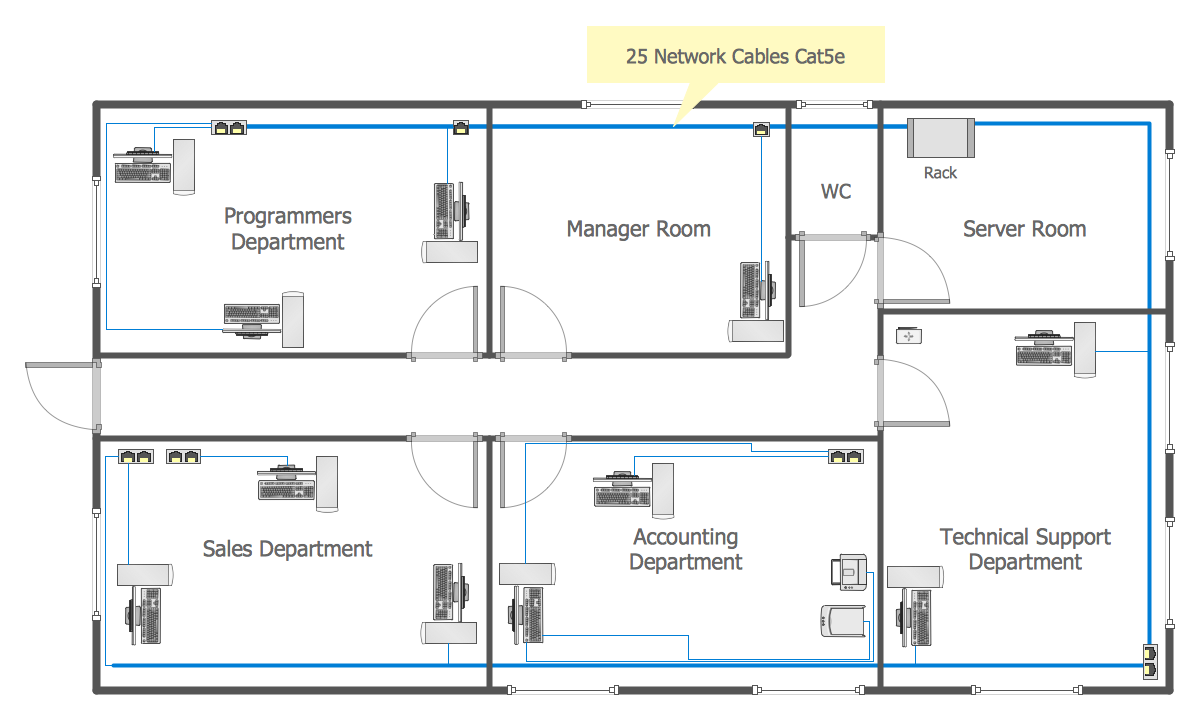
Example 3. Network Mapper - Network Floor Plan Layout
The samples you see on this page were created in ConceptDraw DIAGRAM using the Network Layout Floor Plans Solution for ConceptDraw DIAGRAM These network floor plans successfully demonstrate solution's capabilities and professional results you can achieve with network mapper ConceptDraw DIAGRAM An experienced user spent 10 minutes creating every of these samples.
Use the Network Layout Floor Plans Solution for ConceptDraw DIAGRAM software to create your own diagrams, schemes and plans of any complexity quick, easy and effective, and then successfully use them.
All source documents are vector graphic documents. They are available for reviewing, modifying, or converting to a variety of formats (PDF file, MS PowerPoint, MS Visio, and many other graphic formats) from the ConceptDraw STORE. The Network Layout Floor Plans Solution is available for all ConceptDraw DIAGRAM or later users.
FOUR RELATED HOW TO's:
Computer networks nowadays are spread all across the world. The large number of parameters, such as geographic scale or communication protocols, can divide networks. One of the most common types of networks is called local area network (LAN). It convenient to represent network examples by means of diagrams.
This local area network (LAN) diagram provides an easy way to see the way the devices in a local network are interacted. The diagram uses a library containing specific symbols to represent network equipment , media and the end-user devices such as computers (PC, mac, laptop) , network printer, hubs, server and finally a modem. There are two types of network topologies: physical and logical. The current diagram represents precisely a physical type of LAN topology because it refers to the physical layout of a local network equipment.
Picture:
What is a Local Area Network?
Examples of LAN Diagrams
Related Solution:
The efficiency of any corporate network depends on many factors such as equipment, architecture etc. Moreover, every administer knows that network architecture is a cornerstone for any system. Also, it's easy to make a draft of a network structure using an appropriate diagramming tool.
Designing network architecture diagrams refers to the network structure, including hardware, software, connectivity, protocols of communication and type of transmission: wired or wireless. A high performance, highly reliable, and secure network architecture is critical for the successful deployment and operation of modern communication network. This diagram represents in detail the sample of the network architecture of the three-divisional office. It is designed using vector libraries supplied with ConceptDraw Computer and Networks solution.
Picture: Network Architecture
Related Solution:
If we divide computer networks by scale, we get several main categories. The smallest network is PAN, as it connects personal devices themselves, and as the number of users grows, a local area network can be recognized, and campus area networks (CAN) connects several local networks located within some area like a university or a corporation. Computers connected to CAN share public educational materials and list of CAN network examples includes such prestigious universities like Stanford and Carnegie Mellon.
This is an example of a computer network diagram created for a campus area network. It was created using using ConceptDraw solution for the Computer and Network diagramming. The specific of this sample campus network is its distribution. It is rather broad to embrace a big campus territory. This diagram can be applied as a template for designing custom area network topology diagram for a particular educational institution.
Picture: Campus Area Networks (CAN). Computer and Network Examples
Related Solution:
To connect two or more network devices are used the network cables. There are more different types of the network cables: Coaxial cable, Optical fiber cable, Twisted Pair, Ethernet crossover cable, Power lines and others. They are used depending of the network topology, size, protocol.
This example was created in ConceptDraw DIAGRAM using the Computer and Networks solution from the Computer and Networks area of ConceptDraw Solution Park.
Picture: Network wiring cable. Computer and Network Examples
Related Solution:


