P&ID Diagram Software
Piping and Instrumentation Diagram (P&ID) is a detailed technical schematic used to design the layout of engineering process systems and control the systems and industrial processes at the plants. It depicts the entire engineering process related to the development and installation of a process plant, shows the mechanical aspects of the plant, but without excessive details. P&ID shows interconnections of the main industrial process equipment, machinery, sensors, and installed instrumentation devices by a system of pipelines. These diagrams allow monitoring and control of the flow of materials, liquids, or other components through the pipelines.
P&IDs contain detailed mechanical information about equipment and components of a physical process flow, safety and regulatory requirements, procedures, start-up and operational information. Specifications for installation, configuration, modification, and maintenance of equipment, instruments and operational systems at the plants and processing facilities, and safety requirements are also included. Piping and Instrument Diagrams are more detailed diagrams than Process Flow Diagrams. At the same time, P&IDs provide relative sizes and positions of the equipment, not actual ones.
Piping and Instrument Diagrams have a wide list of applications and are the base of any process plant. They are used in totally different engineering projects, for chemical and manufacturing plants, refinery industries, etc. P&IDs are invaluable documents for electrical engineers, instrument engineers, piping designers, mechanical technicians, operators, installers, safety personnel, and other technical experts. These are the primary diagrams to begin and plan the plant construction, build it, guide the design and implementation, set up a plant operation, and then maintain safety, control the process flow, modify and streamline existing processes. Piping and Instrument Diagrams are necessary when setting up heat exchangers, steam or electric boilers, and many other equipment. P&ID needs to be kept on hand at each stage of plant construction and maintenance, to be reviewed when necessary, especially when something goes wrong. It helps to fix any troubleshooting, manage changes, improve processes, replace a piece of equipment. P&IDs are also useful in training workers and contractors. The process components and the entire plant sections require modifications over time and P&ID plays a vital role in the process of maintenance, modification, improvement, and tracking changes.
P&ID diagrams often contain additional details regarding the equipment such as size, material, throughput, rating, utility usage, etc. At the same time, P&IDs aren't exact models and aren’t necessarily drawn to scale or geometrically accurate. According to the goals, these are more or less detailed schematics. Separate diagrams may be created to elaborate some segments. P&IDs are the base for schematics of control, start-up and shutdown systems, with accounting requirements for safety and regulation. The fundamental safety requirements involve obligatory including of the safety elements in P&IDs and then to the plant.

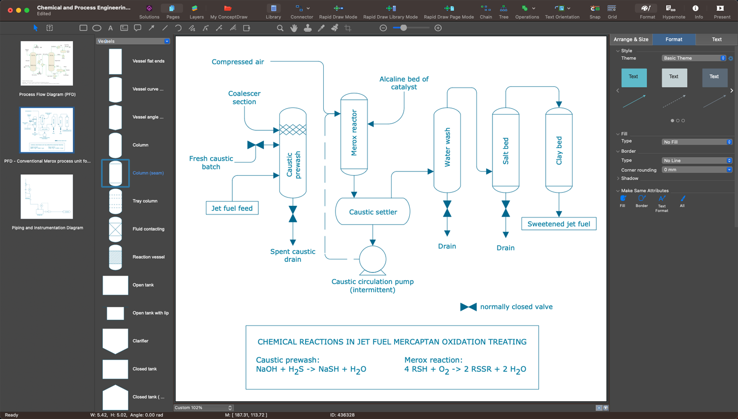
Example 1. P&ID Diagram Software — ConceptDraw DIAGRAM
Piping and Instrument Diagrams are standardized diagrams issued and used at various stages of the project. They use specific notation, shapes and symbols of mechanical equipment, instruments, bypass lines, sensors, actuators, controllers, valves, vessels, pumps, reducers, vents, drains, drivers, heat exchangers, piping components, and many other items. The symbols may contain letters and numbers to indicate different parameters like temperature, a number in the system, or others, and help to create clear and understandable Piping and Instrumentation Diagrams.
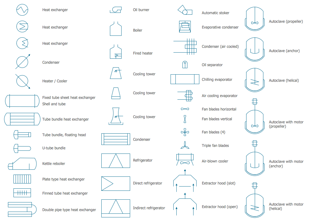
Example 2. Heating Equipment Library
Creating a P&ID diagram is a complicated process, but professional drawing software makes easier the drawing process. ConceptDraw DIAGRAM with Chemical and Process Engineering solution is a powerful and user-friendly vector drawing software with amazing features and a significant number of detailed symbols and icons that make designing Piping and Instrumentation Diagrams of any complexity fast and easy. Chemical and Process Engineering solution contains 8 libraries with 468 vector design elements — heating equipment, industrial equipment, instruments, pumps, vessels, valves, fittings, process annotation symbols, and many other symbols. It is perfect for use by technical specialists, engineers, industry professionals, educators and students of engineering faculties.
Create unique content for industrial, business, and individual purposes easily. Show the connectivity in a control system and process sequence. Store your diagrams in electronic form or print, share with colleagues by email or in social media, on thematic websites, in reports and presentations. ConceptDraw DIAGRAM is excellent P&ID diagram software for both beginners and professional engineers to create P&ID and save time on documentation.
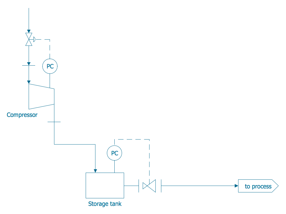
Example 3. Piping and Instrumentation Diagram Template
The set of P&ID Diagrams you see on this page was created in ConceptDraw DIAGRAM software using the Chemical and Process Engineering Solution. These samples successfully demonstrate solution's capabilities and professional results you can achieve. An experienced user spent 10-20 minutes creating each of them.
Use the Chemical and Process Engineering Solution for ConceptDraw DIAGRAM software to create your own professional-looking P&ID Diagrams and Process Diagrams of any complexity quickly, easily and effectively, and then successfully use them in your work and scientific activity.
All source documents are vector graphic documents. They are available for reviewing, modifying, or converting to a variety of formats (PDF file, MS PowerPoint, MS Visio, and many other graphic formats) from the ConceptDraw STORE. The Chemical and Process Engineering Solution is available for all ConceptDraw DIAGRAM users.

