P&ID Drawing Program
Piping and Instrumentation Diagram (P&ID) is a graphical drawing, which illustrates the components of a physical process flow and related piping. Usually, P&IDs are used to show the systems and processes in the engineering area, creating accurate depictions of piping structures and other related components. They include specifications of the plant processing, outline materials for construction and other details. Piping and Instrumentation Diagrams are essential in engineering and process industries, to create documentation for process industry facilities, chemical and manufacturing plants, and other industries. They contain critical information for the smooth and efficient operation of the process industries.
P&ID is a schematic drawing, which gives a primary visual representation of a process control system and is an essential part of the plant development process. These diagrams are used to operate the process system, maintain and modify the processes that they describe. P&IDs include the essential components, process equipment, process components, control devices, control interlocks, and instrumentation connected with piping. They show the physical sequence of components and branches, control and shutdown components, include safety and regulatory requirements. P&IDs contain start-up and operational information, and safety elements to remove potential hazards and harmful impacts on the environment or minimize the risks associated with them. The inclusion of safety features is incredibly important because many hidden hazards affect the proper operation of a plant. Dealing with them at the early stages is vital to avoid problems in the development process and further plant construction and operation.
P&ID is crucial in all stages of process system development, design, layout, construction, installation, and operation of a system. It shows the physical sequence of equipment and systems, and how they are connected. Usually Piping and Instrumentation Diagram (P&ID) is developed based on a Process Flow Diagram (PFD) designed at the stage of plant planning and is an extension of it providing more details. In its turn, P&ID is often used as the basis for the development of system control and safety schemes, startup and shutdown schemes, realization of operational investigations and analysis. P&IDs are an essential basis for developing documentation and specifications.
P&IDs reflect schematically the process of the system, functional relationships between piping, instrumentation, and system equipment units, at the same time often without indicating the precise physical location of the components in scale. Process plants use numerous types of equipment to produce specific products from raw materials and they often differ based on the kind of industry. All used equipment and instrumentation are shown with standardized symbols, shapes, and designations on the diagram. These include symbols for process and supporting equipment, handling equipment, chemical storage equipment, water and wastewater treatment equipment, fire protection equipment, piping, valves, vessels, drums, heat exchangers, gas or steam turbines, piping, pumps, instruments, vents, drains, swaggers, fittings, reducers, increasers, compressors, sampling lines, start-up and flush lines, interlocks, reactors, furnaces, tanks, cooling towers, boilers, columns, towers, loading and unloading arms, fuel systems, air systems, flaring systems, control inputs and outputs, computer control system, etc.
Often the equipment has unique identification codes, which define specific parameters like size, fluid content, material, status, connection methods, and other characteristics from the equipment data sheet. These codes are unified in the industrial world and include letters and numbers. Unique tags help uniquely identify all equipment and being outlined in the diagram, they give engineers detailed information about equipment. Usually, the flow directions are also indicated.

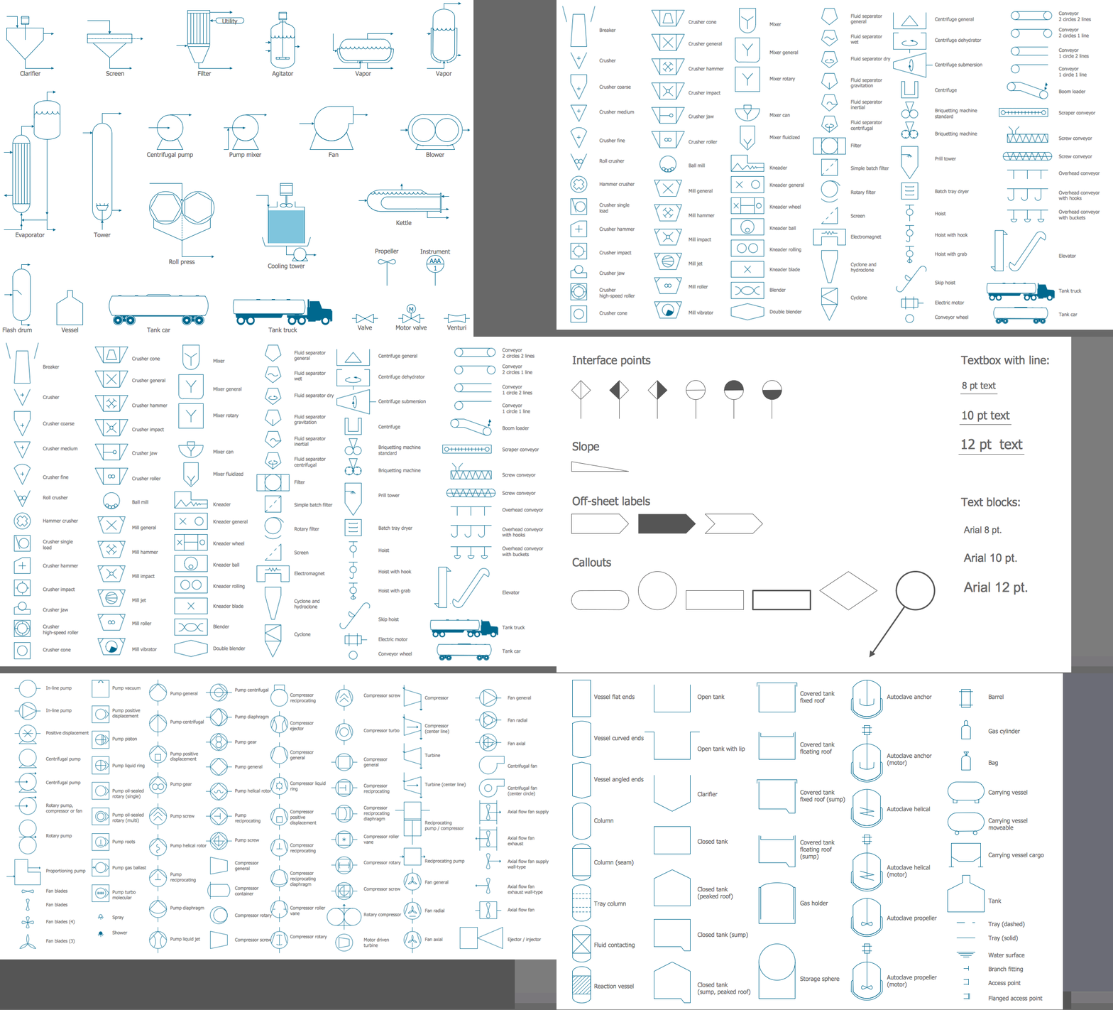
Example 1. P&ID Drawing Program - ConceptDraw DIAGRAM Solution Libraries
ConceptDraw DIAGRAM with included Chemical and Process Engineering solution is a simple and convenient way to create Piping and Instrumentation Diagrams at the stage of your plant design, planning, construction, and maintenance. The solution includes a huge variety of the most popular standardized symbols from different industries collected in 8 libraries. These are design elements — instruments, heating equipment, valves, vessels, pumps, fittings, and other instruments and process annotation symbols. Show easily the physical sequence of equipment and systems, and how the system components are connected with piping. The intuitive drawing tools, libraries of ready-made vector design elements, formatting tools, and other features offered by ConceptDraw DIAGRAM are useful for P&ID design.
ConceptDraw DIAGRAM is a streamlined P&ID drawing program that makes creating Piping and Instrumentation Diagrams an easy and comfortable process for all technical specialists, electrical, mechanical, and process engineers, piping designers, technical developers, and other stakeholders. Accurate design elements help to maintain and modify your processes, keep track of basic operational details, and control plant operation easily.
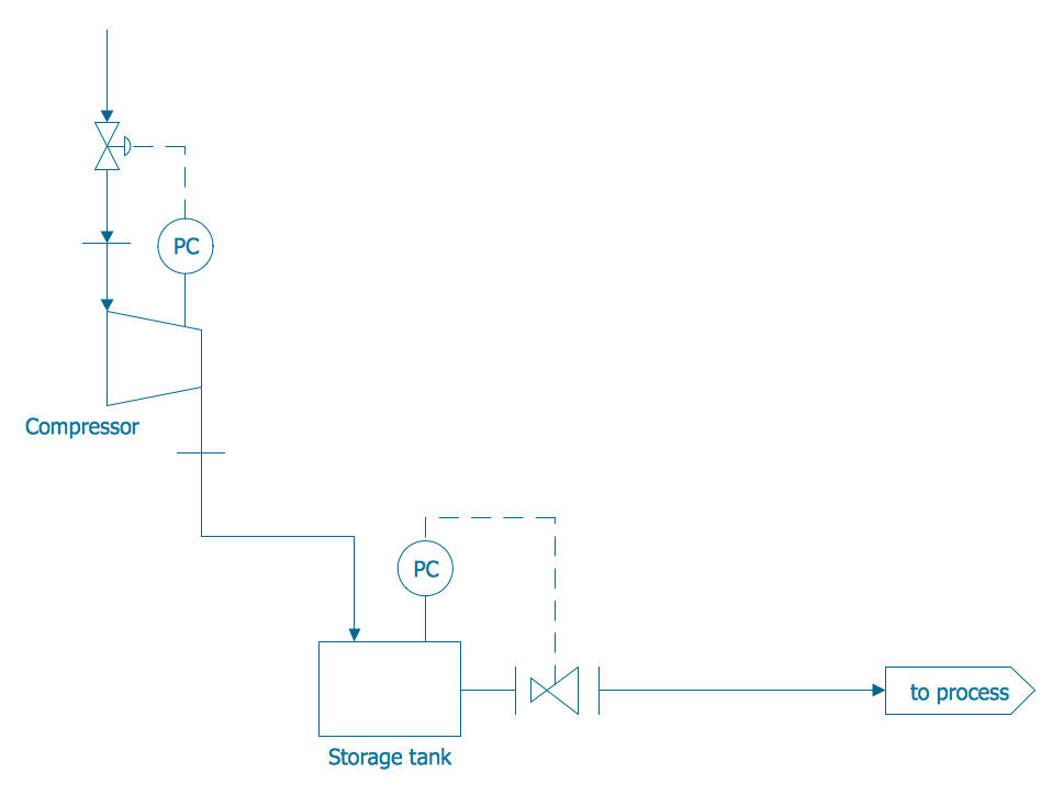
Example 2. Piping and Instrumentation Diagram Template
P&IDs developed for a plant by process design engineers are included in technical documentation and are useful for technical specialists at all further steps including instrumentation and piping engineers, builders, operators, and maintenance specialists. They play a significant role in the construction plants, maintenance and modification of the processes, discussion, repairs, and replacements. Use them to train employees, to demonstrate to them the key points of process system operation to operate and maintain the system correctly, and for further analysis and modification of the system to improve its performance. Provide your team with a universal understanding of the system and industrial process. Easily manage, analyze, update, and share your P&IDs with all stakeholders.
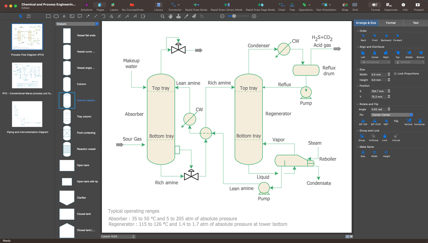
Example 3. P&ID - Amine Treating Unit
The set of P&ID Diagrams you see on this page was created in ConceptDraw DIAGRAM software using the Chemical and Process Engineering Solution. These samples successfully demonstrate solution's capabilities and professional results you can achieve. An experienced user spent 10-20 minutes creating each of them.
Use the Chemical and Process Engineering Solution for ConceptDraw DIAGRAM software to create your own professional-looking P&ID Diagrams and Process Diagrams of any complexity quickly, easily and effectively, and then successfully use them in your work and scientific activity.
All source documents are vector graphic documents. They are available for reviewing, modifying, or converting to a variety of formats (PDF file, MS PowerPoint, MS Visio, and many other graphic formats) from the ConceptDraw STORE. The Chemical and Process Engineering Solution is available for all ConceptDraw DIAGRAM users.

