SDL Flowchart Symbols
SDL diagram is a type of diagram which uses the graphical elements of Specification and Description Language (SDL) for designing the object-oriented diagrams, for modeling state machines in communication, telecommunication, aviation, automotive and medical industries, for creating specifications and descriptions of behavior, data, and inheritance for interactive real-time systems, reactive and distributed systems. SDL diagram is constructed of standard SDL elements (objects) which are designed according to International Telecommunications Union standards.
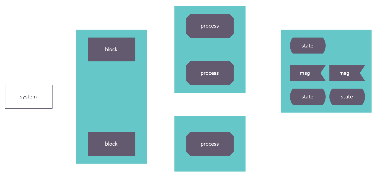
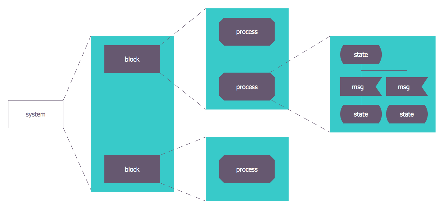
The SDL diagram consists of three building blocks: system definition which defines the major blocks (nodes) of the system such as clients and servers, block charts which show the details and process diagram which show the processing steps in each block. Arrows connect the objects and show the flow of control. The Start object shows beginning of the diagram.
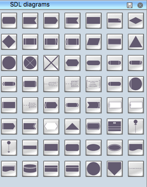
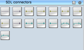
Drawing the diagrams we try to find in help the powerful software and now we have the ConceptDraw DIAGRAM The ability easily create the SDL diagrams is made possible thanks to unique Specification and Description Language (SDL) Solution from the Industrial Engineering Area of ConceptDraw Solution Park. This solution extends ConceptDraw DIAGRAM with 2 libraries - SDL Connectors and SDL Diagrams that contain 71 predesigned SDL flowchart symbols.

Example 1. SDL Diagrams Symbols Library
Turn attention for this enormous collection of predesigned vector objects which let design the SDL diagram of any complexity and degree of detailing in mere minutes.

Example 2. SDL Connectors Symbols Library
Try design your own SDL diagram in ConceptDraw DIAGRAM and make sure that is very easy! With powerful drawing tools of ConceptDraw DIAGRAM you don't need to be an artist, you can concentrate on your work and simply drag and use ready objects developed for you by professional designers.

Example 3. SDL Flowchart Symbols
Follow the next few steps to create the SDL diagram:
- add the objects to your diagram simply dragging them from the SDL Diagrams library to your document page and arrange them;

Example 4. Adding the Objects to SDL Diagram
- add text to the objects - double-click an object to activate the text editing mode and type the text;

Example 5. Adding the Text to Objects
- connect the diagram objects using the connectors from the SDL Connectors library and add to text to connectors the same way you add text to objects, if needed.

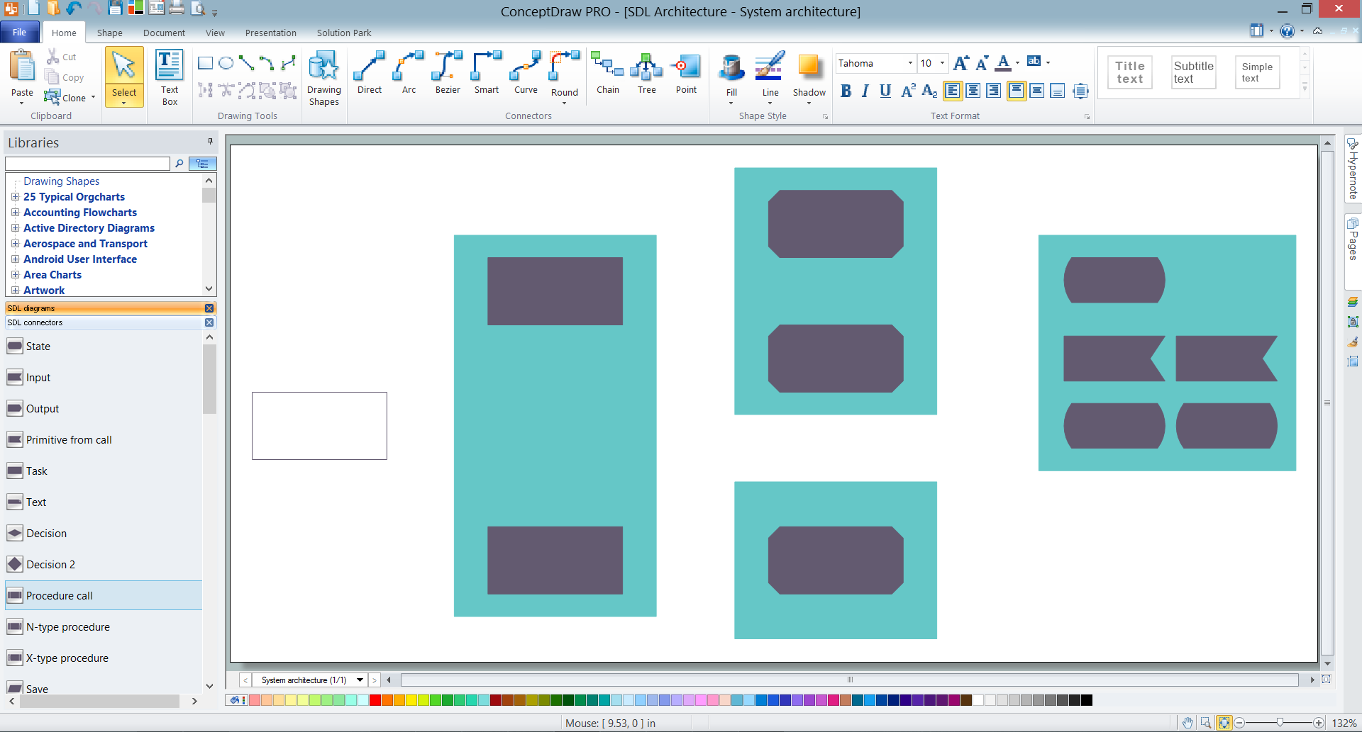
Example 6. SDL Architecture
Each SDL diagram designed in ConceptDraw DIAGRAM can be then easy printed to share with colleagues, send via e-mail directly from the program, exported to various formats, including PPT, PDF, MS Visio, HTML, and many other popular graphic formats.
-Solution.png "Specification and Description Language (SDL) Solution")
Example 7. Specification and Description Language (SDL) Solution
Owing to the Specification and Description Language (SDL) solution and its powerful tools, the ConceptDraw DIAGRAM diagramming and vector drawing software is the best for easy drawing the SDL Diagrams to represent telecommunication systems, automotive systems, remote control systems, railway control systems, robotic systems, and more other.
TEN RELATED HOW TO's:
Easy charting software comes with beautiful chart templates and examples. This makes it easy to create professional charts without prior experience.
Picture: Chart Examples
Related Solutions:
Do you need to draw a check order process flowchart?
Use the intuitive product - ConceptDraw.
Picture: Check Order Process Flowchart. Flowchart Examples
Related Solution:
This sample shows the Data Flow Diagram of the Taxi Service and interactions between the Clients, Operators and Divers, as well as Orders and Reports databases.
Picture: Taxi Service Data Flow DiagramDFD Example
Related Solution:
A voltage source is a two terminal device which can maintain a fixed voltage. An ideal voltage source can maintain the fixed voltage independent of the load resistance or the output current. However, a real-world voltage source cannot supply unlimited current. A voltage source is the dual of a current source. Real-world sources of electrical energy, such as batteries, generators, and power systems, can be modeled for analysis purposes as a combination of an ideal voltage source and additional combinations of impedance elements.
26 libraries of the Electrical Engineering Solution of ConceptDraw DIAGRAM make your electrical diagramming simple, efficient, and effective. You can simply and quickly drop the ready-to-use objects from libraries into your document to create the electrical diagram.
Picture: Electrical Symbols — Power Sources
Related Solution:
Apply Electrical Engineering solution for ConceptDraw DIAGRAM and numerous electric circuit symbols to 🔸 develop and illustrate all types of electrical circuits as ✔️ electrical circuit diagrams, ✔️ electrical schematics, ✔️ electrical diagram drawings
Picture: Electrical Circuits — Electrical Symbols
Related Solution:
ConceptDraw DIAGRAM diagramming and vector drawing software extended with Specification and Description Language (SDL) Solution from the Industrial Engineering Area of ConceptDraw Solution Park provides powerful drawing tools for quick and easy creating well-designed FSM diagrams.
Picture: FSM — Finite-state Machine
Related Solution:
Learn about Systems Engineering, its process and discover practical examples illustrated through diagrams. ✔️ How to draw Systems Engineering diagrams using the ConceptDraw DIAGRAM software?
Picture:
What is a Systems Engineering?
Examples of Systems Engineering Diagrams
Related Solution:
Chart Audits, Chart Auditor - Designing the chart auditor can use the audit flowchart symbols from the Audit Flowcharts library for Audit Flowcharts Solution. Moreover it is convenient to use anyone of samples or templates offered by Audit Flowcharts Solution and design its own chart audits and audit flowcharts on the base of them.
Picture: Chart Audits. Chart Auditor
Related Solution:
ConceptDraw defines some map types, divided into three categories. Every map type has specific shapes and examples.
Picture: Types of Map - Overview
Related Solution:
The AWS Architecture Diagrams solution includes icons, sample and templates for several Amazon Web Services products and resources, to be used when creating architecture diagrams. The icons are designed to be simple so that you can easily incorporate them in your diagrams and put them in your whitepapers, presentations, datasheets, posters or any technical material you like.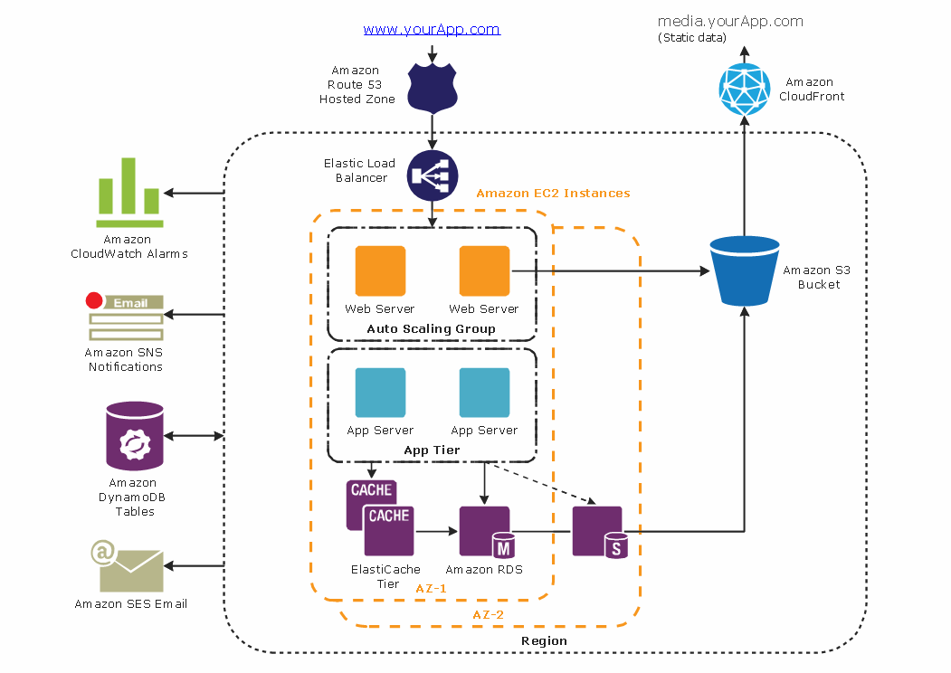
Picture: Diagramming tool - Amazon Web Servicesand Cloud Computing Diagrams
-Solution.png "Specification and Description Language (SDL) Solution")