Three-phase Power
Three-phase electric power is a common type of polyphase electrical system using three active wires called phases to deliver three independent alternating electrical currents of the same frequency and voltage amplitude. These wires have a phase difference of one-third of a cycle or 120 degrees out of phase that provides constant power transfer to a balanced linear load. Maximum and minimum oscillations are compensated and producing a rotating magnetic field with a specified direction and constant magnitude in an electric motor is possible. This simplifies the design of electric motors. However, it is important that phases be correctly connected to achieve the intended direction of rotation of three-phase motors. Wiring for the three-phase systems is typically indicated by colors that can vary by country.
In addition, the phase currents cancel one another, the current in each of the three conductors equals in magnitude to the sum in two others with the opposite sign. As a result, the sum of the instantaneous currents of the conductors equals zero.
Sometimes three-phase electrical power can include a fourth additional neutral return wire, which is grounded at the switchboard and allows the system to use a higher voltage and support several separate lower-voltage single-phase appliances.
Three-phase electrical power was developed in the 1880s. Currently, it is the most common worldwide method to generate, transfer and distribute alternating current power used by electrical grids. It is used to power large induction motors, electric motors, and other heavy loads.
Three-phase systems are an efficient form of electrical power distribution, increasing the efficiency of electrical equipment and its durability.
Three-phase electric power is an AC system. It is economical and uses less conductor material than a two-wire single-phase circuit to transmit electrical power. It is also more efficient and delivers greater power and more stable flow of electricity than single-phase. The use of transformers in three-phase circuits allows changing voltages. It is easily raised for effective transmission or reduced for distribution.
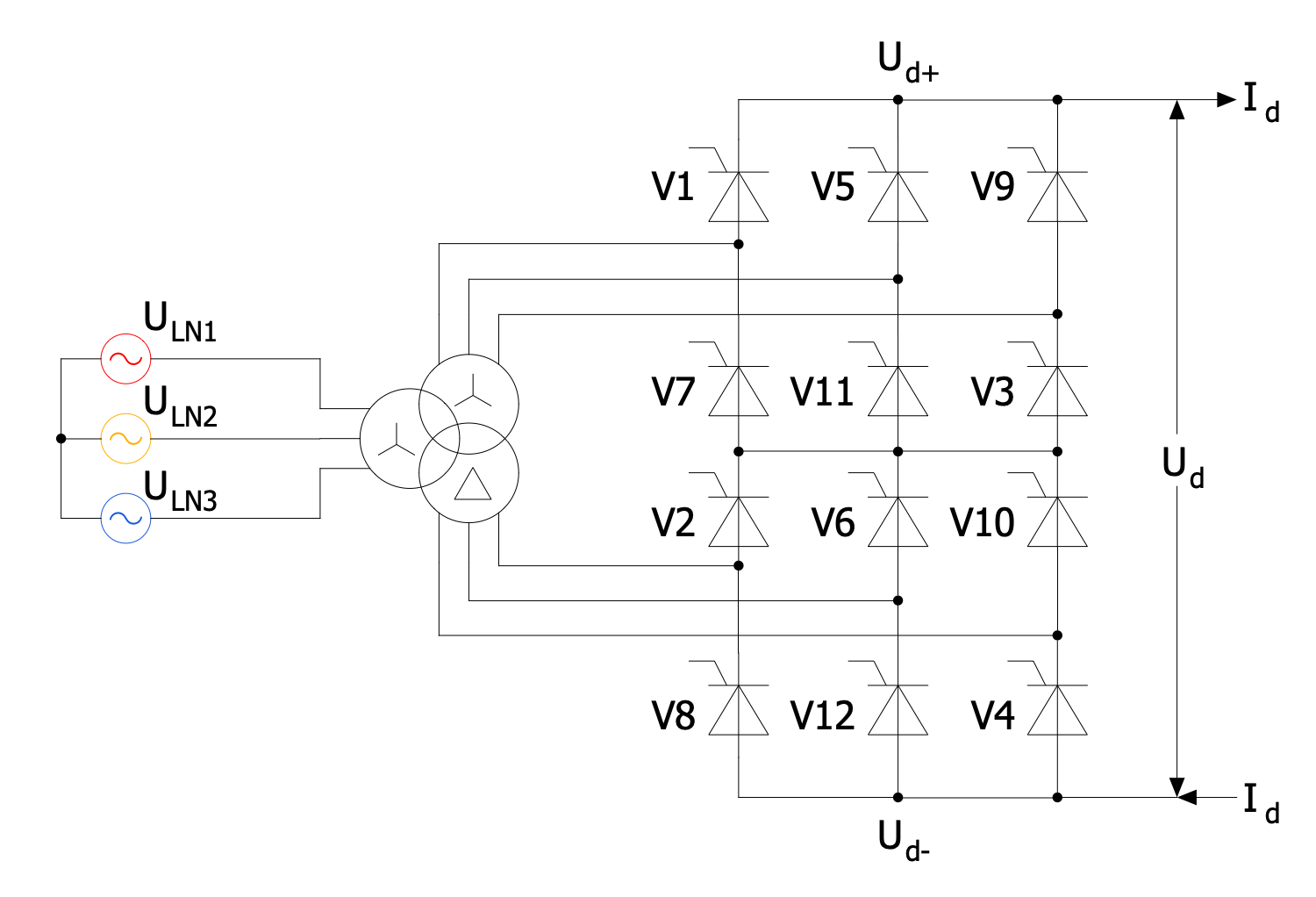
Example 1. Three-phase Power Diagram
Usually, three-phase power is used in commercial and industrial buildings with power-hungry machinery, data centers, server rooms, and large homes with multiple electric appliances, especially those which require larger power to avoid power fluctuation. This equipment includes fridges and freezers, large filter pumps for pools, industrial fans, blowers, big electric motors with power of more than 2 kilowatts, welder equipment, ducted air conditioning equipment, electric boilers, pumps, compressors, large rectifier systems, kilns to do ceramics, systems converting alternating current to direct current, and more equipment.
Three-phase power is supplied into the properties constantly, without peaks and valleys through underground or overhead lines. Modern electrical equipment operating on constant power has advantages, uses less energy and provides smooth, constant, and efficient power, nearly twice bigger as the power of single-phase systems. At the same time, they allow using less expensive cabling and other components. However, it is important to track the load on each circuit and not exceed circuit capacity.

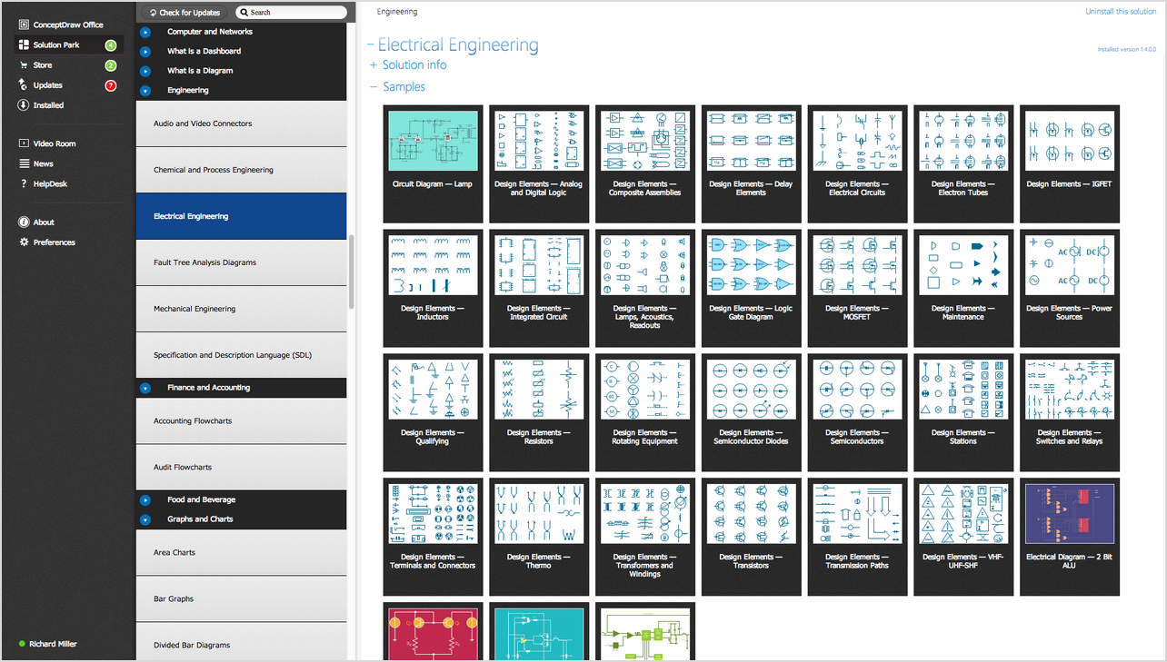
Example 2. Power Circuits Solution Libraries Design Elements
ConceptDraw DIAGRAM software offers the Power Сircuits solution with a large collection of varied vector stencil libraries and samples for easy and effective design of professionally looking Electrical circuits of various kinds including Three-phase power diagrams. The solution's libraries include design elements — three phase transformers, three-phase alternators, three-phase generators, three-phase converters, three-phase motors, three-phase wire connections, and many more elements.

Example 3. Double Fed Asynchronous Machine
The Electrical circuit samples you see on this page were created in ConceptDraw DIAGRAM software using the drawing tools of the Power Сircuits Solution. These examples successfully demonstrate the solution's capabilities and the professional results you can achieve using it. An experienced user spent 5-10 minutes creating each of these samples.
Use the drawing tools of the Power Сircuits solution to design your own Electrical Circuit diagrams, schematics, and layouts quick, easy, and effective.
All source documents are vector graphic documents. They are available for reviewing, modifying, or converting to a variety of formats (PDF file, MS PowerPoint, MS Visio, and many other graphic formats) from the ConceptDraw STORE. The Power Сircuits Solution is available for ConceptDraw DIAGRAM users.