Transmission Lines
A transmission line is an electrical engineering term used for a specialized cable (conductor), which conducts electromagnetic waves and carries a large amount of high-voltage electrical power from the generating substation to various distribution units. The transmission line's conductor has a uniform cross-section and conducts high-voltage direct current.
The high and strong electrical towers made up of steel are used to support the conductors of the transmission line. The high distance between the line and the ground is kept for safety purposes. Transmission lines use antennas as feed lines and connect receivers and radio transmitters with these antennas.
The transmission lines are affected by several parameters, which determine transmission efficiency, voltage regulation, line loss, performance, and stability of the system. These include length, capacitance, resistance, inductance, power factor, and shunt conductance.
One differs three types of transmission lines according to lengthwise: short with length of fewer than 50 miles (80km), medium with length from 50 miles (80 km) up to 150 miles (250 km), and long transmission lines with length of more than 150 miles (250 km). Most of the transmission lines are sufficiently long, like the telegraph lines for which they were initially developed. However, short and medium transmission lines are also used. For example, RF engineers use short-printed planar transmission lines for filters. The voltage level of transmission lines also differs from 69 kV to 133 kV.
The air between the conductors acts as an insulating or dielectric medium and forms the capacitor to store the electrical energy. This increases the line's capacitance, which is defined as the charge count per unit of potential difference. Some current can flow in the dielectric medium at the alternating voltage applied in a conductor. It is called leakage current and depends on various atmospheric conditions and pollution. Capacitance is one of the most important parameters of long transmission lines. Its effect is negligible in short transmission lines and presents beginning from medium ones.

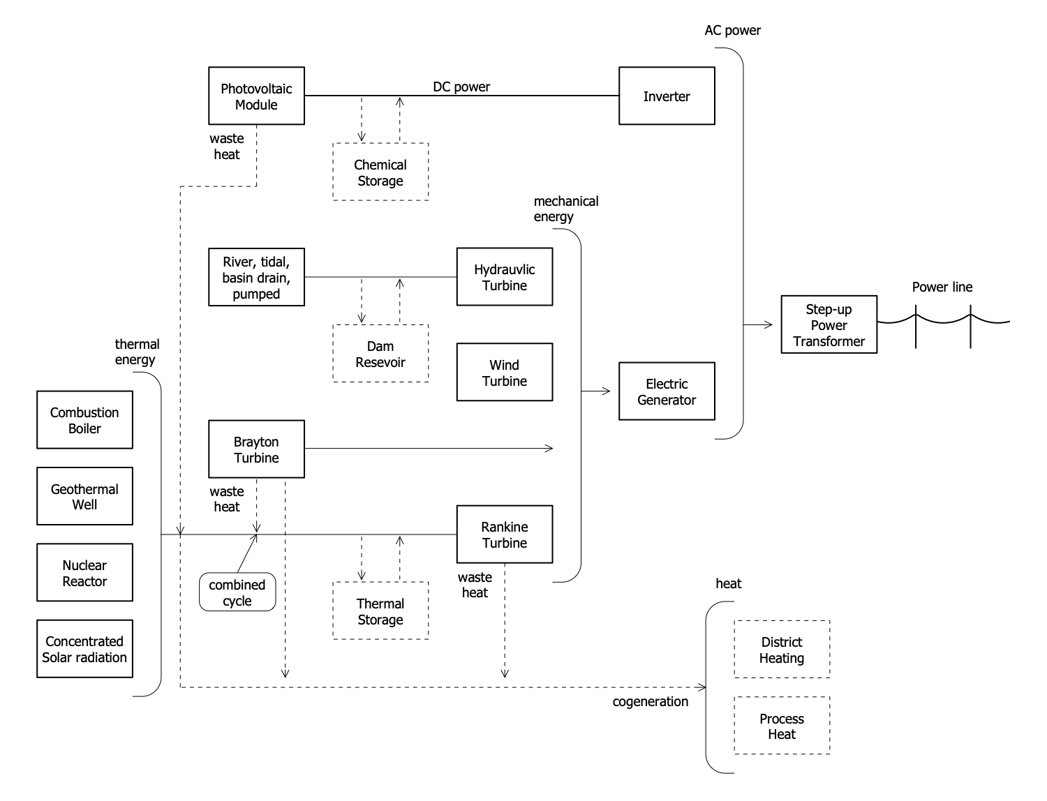
Example 1. Transmission Lines in Electrical Engineering
The current, which flows in the transmission line induces the magnetic flux. The change of current causes the change of magnetic flux and emf appearance in the circuit.
The performance of the transmission line includes the calculation of current, voltage, and power factor at the end of the line. It also considers power loss in the lines and limits of power flows during both steady and transient states. The efficiency of the transmission line is defined as the ratio of the input power to the output power. The admittance of an electrical circuit measures the efficiency of a transmission line and allows flowing AC without any obstruction. In turn, the impedance is an inverse characteristic of admittance and measures difficulties in flowing current through the transmission line.
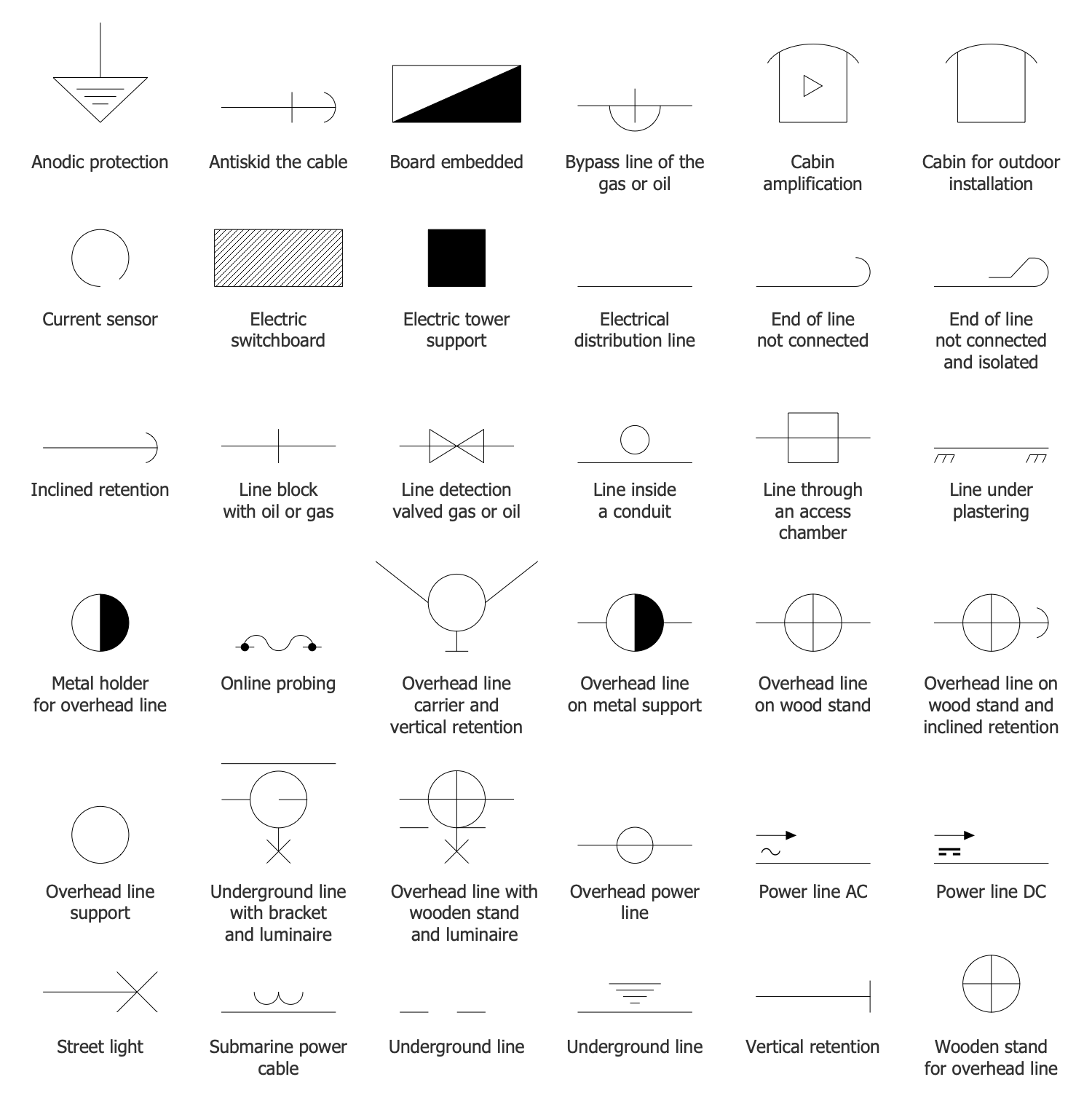
Example 2. Transmission Lines Electrical Distribution Library Design Elements
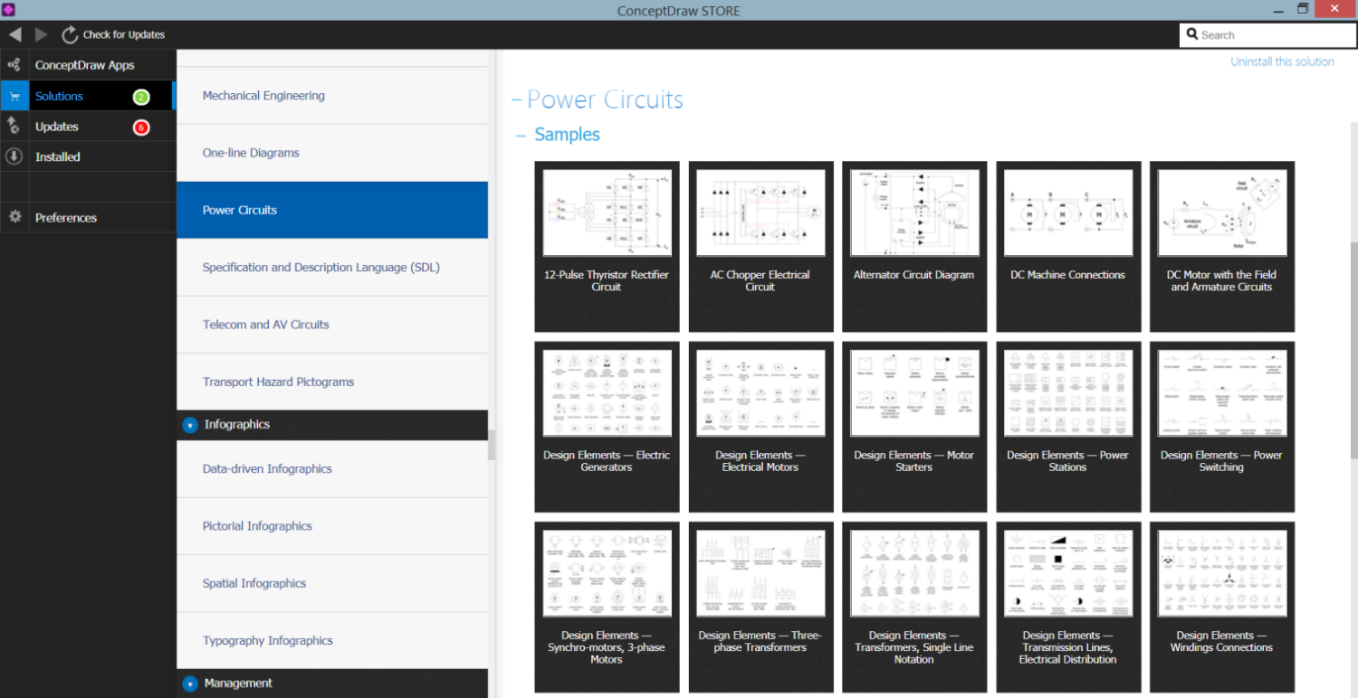
Striving to find effective software to develop electrical equipment and create professional-looking Electrical Circuits, turn your attention to ConceptDraw DIAGRAM software enhanced with Power Сircuits solution. It includes powerful drawing tools, illustrative samples, and large collection of libraries with vector design elements — transmission lines electrical distribution, transmitters, switches, transformers, electrical motors, electric generators, and many more.
Example 3. Power Circuits Solution in ConceptDraw STORE
The Electrical circuit samples you see on this page were created in ConceptDraw DIAGRAM software using the drawing tools of the Power Сircuits Solution. These examples successfully demonstrate the solution's capabilities and the professional results you can achieve using it. An experienced user spent 5-10 minutes creating each of these samples.
Use the drawing tools of the Power Сircuits solution to design your own Electrical Circuit diagrams, schematics, and layouts quick, easy, and effective.
All source documents are vector graphic documents. They are available for reviewing, modifying, or converting to a variety of formats (PDF file, MS PowerPoint, MS Visio, and many other graphic formats) from the ConceptDraw STORE. The Power Сircuits Solution is available for ConceptDraw DIAGRAM users.

