UI Patterns
The most convenient, useful and right way for software engineers, UI designers, UI developers is to use UI patterns in the process of developing any application for computer devices. The User Interface (UI) patterns are standardized solutions for common design problems.
ConceptDraw DIAGRAM diagramming and vector drawing software offers the ConceptDraw Solution Park with numerous solutions for wide variety fields. One of them is iPhone User Interface solution from the Software Development Area.

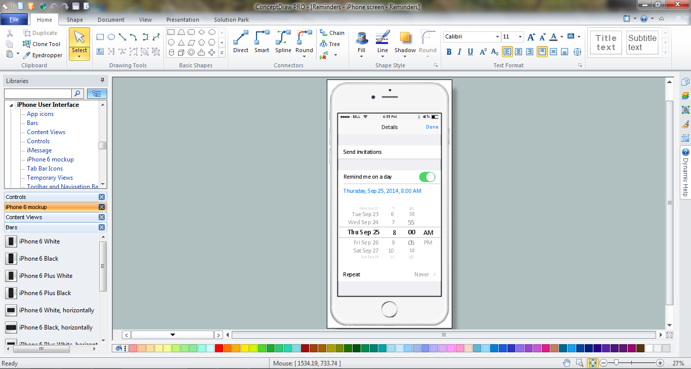
Example 1. iPhone User Interface solution in ConceptDraw DIAGRAM
iPhone User Interface solution can help you illustrate the UI Patterns of any complexity for iPhone mobile device thanks to the predesigned libraries of vector objects and the set of templates and samples.

Example 2. iPhone User Interface Solution in ConceptDraw STORE
9 libraries of iPhone User Interface solution are available from the ConceptDraw DIAGRAM application, templates and samples can be opened for viewing and editing from ConceptDraw STORE.

Example 3. UI Patterns
The iPhone illustrations with UI patterns designed in ConceptDraw DIAGRAM are professional looking and can be successfully used for prototyping and designing the user interfaces and applications for iPhone, for explaining and discussion various UI details in the team, in educational process, etc.
All source documents are vector graphic documents. They are available for reviewing, modifying, or converting to a variety of formats (PDF file, MS PowerPoint, MS Visio, and many other graphic formats) from the ConceptDraw STORE. The iPhone User Interface Solution is available for all ConceptDraw DIAGRAM or later users.
TEN RELATED HOW TO's:
Data storage in clouds is very popular and widely used in the modern world. The Amazon is one of the companies which provide this service. Amazon Web Services offers the inexpensive and reliable cloud computing services, that's why many large companies prefer the Amazon Cloud for storage and operating their data. It is convenient to draw various AWS diagrams explaining the use of amazon cloud with help of tools of AWS Architecture Diagrams Solution from the Computer and Networks Area of ConceptDraw Solution Park.
Picture: Amazon Cloud
Related Solution:
ConceptDraw DIAGRAM is a powerful diagramming and vector drawing GUI software. Extended with Mac OS User Interface solution from the Software Development area, ConceptDraw DIAGRAM is the best software for designing professional looking user interfaces for new OS X 10.10 Yosemite operating system developed for Macintosh computers. Mac OS User Interface solution offers you large quantity of Mac OS templates, samples and user interface design examples.
Picture: Mac OS User Interface Design Examples
Related Solution:
iPhone is a worldwide popular line of smartphones designed and marketed by Apple Inc. First thing that you see taking up the iPhone is its design and interface. It's very important that interface will be convenient and easy to use on a mobile device. That is why every day designers make great efforts to make the really best iPhone interface.
Picture: iPhone Interface
Related Solution:
Information technologies rapidly develope in the modern world. The popularity of electronic and mobile devices is growing every day and entails the need for the new applications. Now the quantity of applications is incredibly large and every day increases, and thus the programming for mobile devices, and particularly the iPhone programming, is increasingly demanded. iPhones are ones of the most worldwide popular smartphones developed by Apple Inc.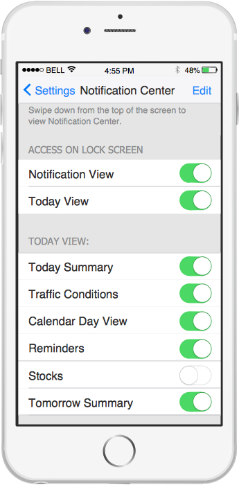
Picture: iPhone Programming
Related Solution:
For documenting the Cloud Computing Architecture with a goal to facilitate the communication between stakeholders are successfully used the Cloud Computing Architecture diagrams. It is convenient and easy to draw various Cloud Computing Architecture diagrams in ConceptDraw DIAGRAM software with help of tools of the Cloud Computing Diagrams Solution from the Computer and Networks Area of ConceptDraw Solution Park.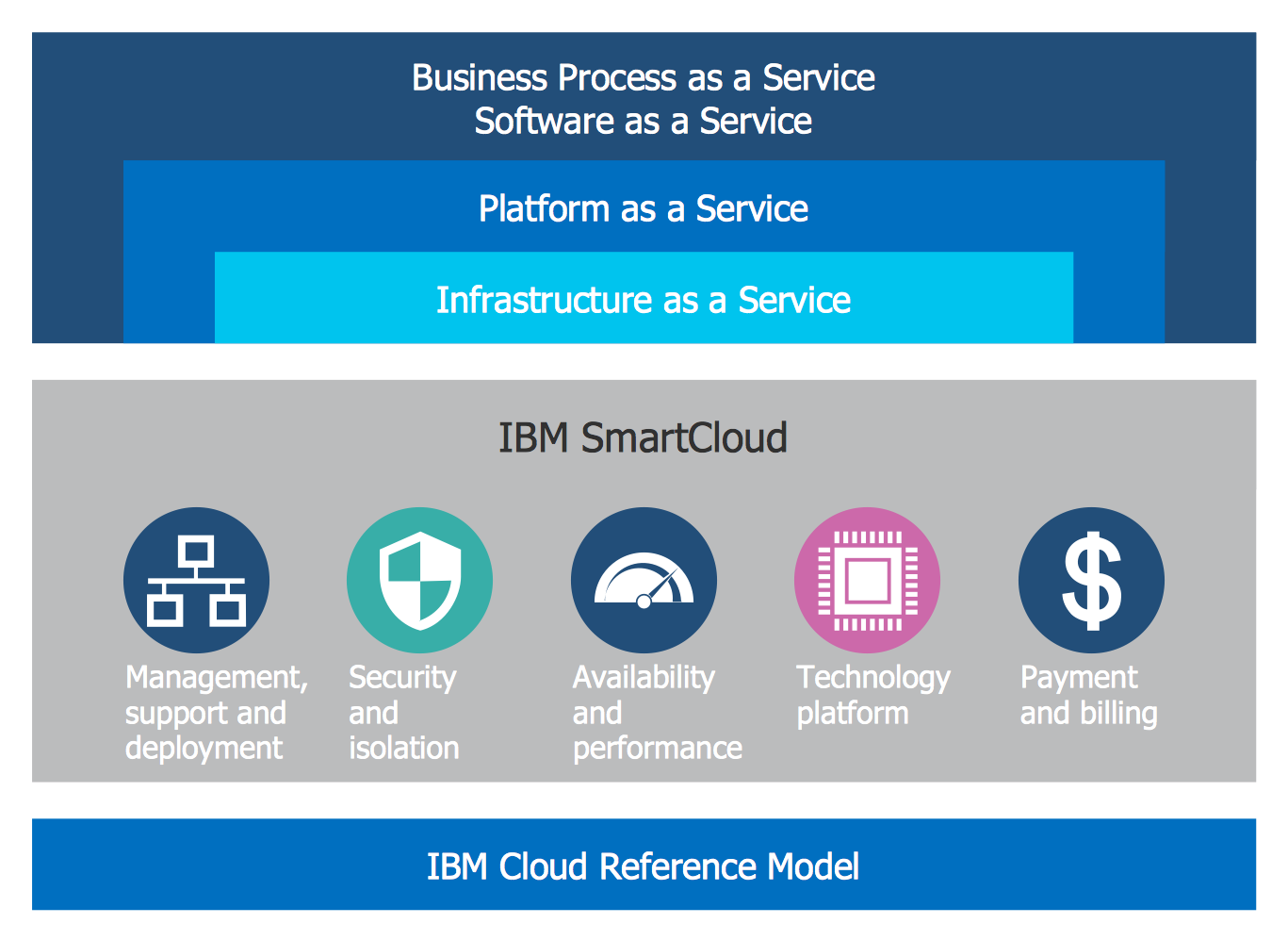
Picture: Cloud Computing Architecture Diagrams
Related Solution:
What is user interface (UI)? User interface of any information device includes everything designed you can interact - the screen you are looking, the icons you are clicking. ConceptDraw DIAGRAM extended with iPhone User Interface Solution is the best diagramming and vector drawing software for designing clear, pleasant and convenient user interfaces. Convenience is the most important moment for users.
Picture: What Is User Interface?
Related Solution:
A flowchart is a powerful tool for examining processes. It helps improving processes a lot, as it becomes much easier to communicate between involved people, to identify potential problems and to optimize workflow. There are flowcharts of different shapes, sizes and types of flowchart vary from quite basic process flowcharts to complex program flowcharts. Nevertheless, all these diagrams use the same set of special symbols like arrows to connect blocks, parallelogram to show data receiving or rectangles for showing process steps.
Basic flowcharts are used to represent a simple process algorithm. A basic flowchart notation consists of rectangles (business processes), arrows (the flow of information, documents, etc.). The same notation is used in items such as the "decision", which allow you to do the branching. To indicate the start of the entire business process and its termination can be used the "Terminator" element. The advantages of Basic Flowchart are simplicity and clarity. With it you can quickly describe the business process steps. Creating of Basic Flowchart does not require any special knowledge, as easily understand by employees with different levels of education and IQ.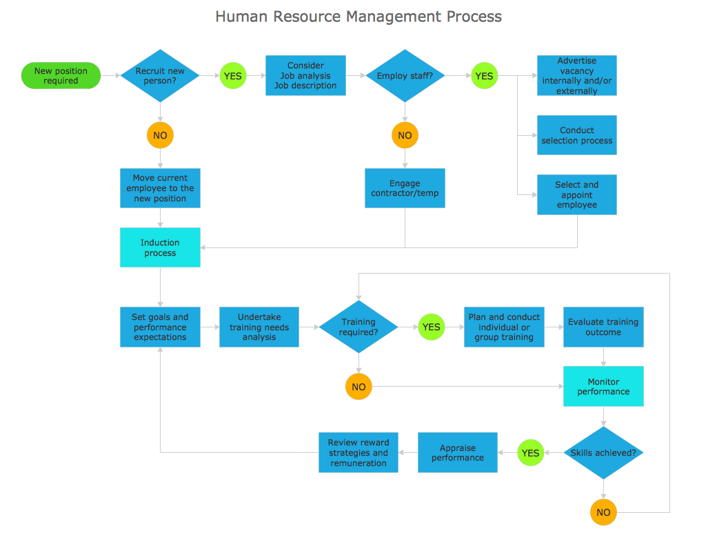
Picture: Types of Flowchart — Overview
Related Solution:
Comparing ConceptDraw DIAGRAM to Omnigraffle - Cross-platform product. While most drawing tools are designed for use on one operating system, ConceptDraw DIAGRAM is available as two independent and concurrent versions on both Macintosh (macOS) and PC (Windows).
License is per named user. That means you can use a single license for Macintosh and PC. Users can install at work and at home with a single license.
Picture: Comparing ConceptDraw DIAGRAM to Omnigraffle
Related Solution:
ConceptDraw DIAGRAM is a powerful diagramming and vector drawing software. Extended with AWS Architecture Diagrams Solution from the Computer and Networks Area, ConceptDraw DIAGRAM now is ideal software for Amazon Web Services diagrams drawing.
Picture: Amazon Web Services
Related Solution: