UML Package Diagram
How To draw UML Package Diagrams
UML Package Diagram depicts the dependencies between the packages that make up a model. There are two special types of dependencies defined between packages:
- package import
- package merge
ConceptDraw has three examples that will help you to start using software for drawing UML Package Diagrams. You can use the appropriate stencils of UML notation for drawing your own UML Package Diagram.
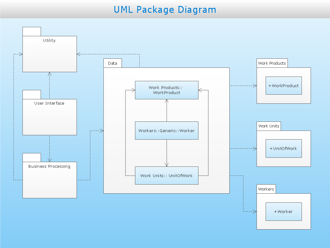
Sample 1. Business process
This UML package diagram sample is created using ConceptDraw DIAGRAM diagramming and vector drawing software enhanced with Rapid UML solution from ConceptDraw Solution Park.
Rapid UML solution provides templates, examples and libraries of stencils for quick and easy drawing all the types of system and software engineering diagrams according to UML 2.4 notation.
Use ConceptDraw DIAGRAM with UML package diagram templates, samples and stencil library from Rapid UML solution to show the dependencies between the packages that make up your system model.
SIX RELATED HOW TO's:
Four lessons explaining how to manage your task list in a Gantt chart. You will learn how to adjust your Gantt chart view, how to add/delete tasks or subtasks, how to change tasks hierarchy, how to show/hide subtasks.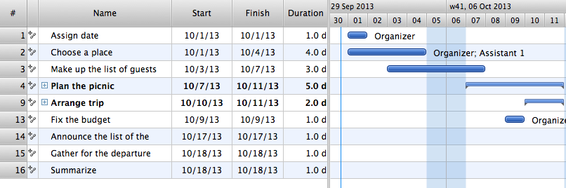
Picture: Managing the task list
There are many ways to track the system in a critical situation. To model a system behavior, uml notation is widely used. Usually, an UML diagram consists of elements such as actor and a case.
This diagram represents the structure of UML notations. Unified Modeling Language (UML) is used in software engineering to depict graphically the software modeling process. UM Language uses graphic notations for developing models of object-oriented systems. These notations displays requirements, sub-systems, logical and physical elements, etc. We created this diagram using ConceptDraw DIAGRAM reinforced with Rapid UML solution. It can be helpful for students on software engineering, when learning UML.
Picture: UML Notation
Related Solution:
The innovative ConceptDraw Arrows10 Technology included in ConceptDraw DIAGRAM Package is a powerful drawing software that changes the way diagrams could be created.
You don't have to guide your connectors, they do this automatically.
Get software for creating business graphics such as charts and graphs, diagrams, organizational charts, multimedia presentations, and visual demonstrations.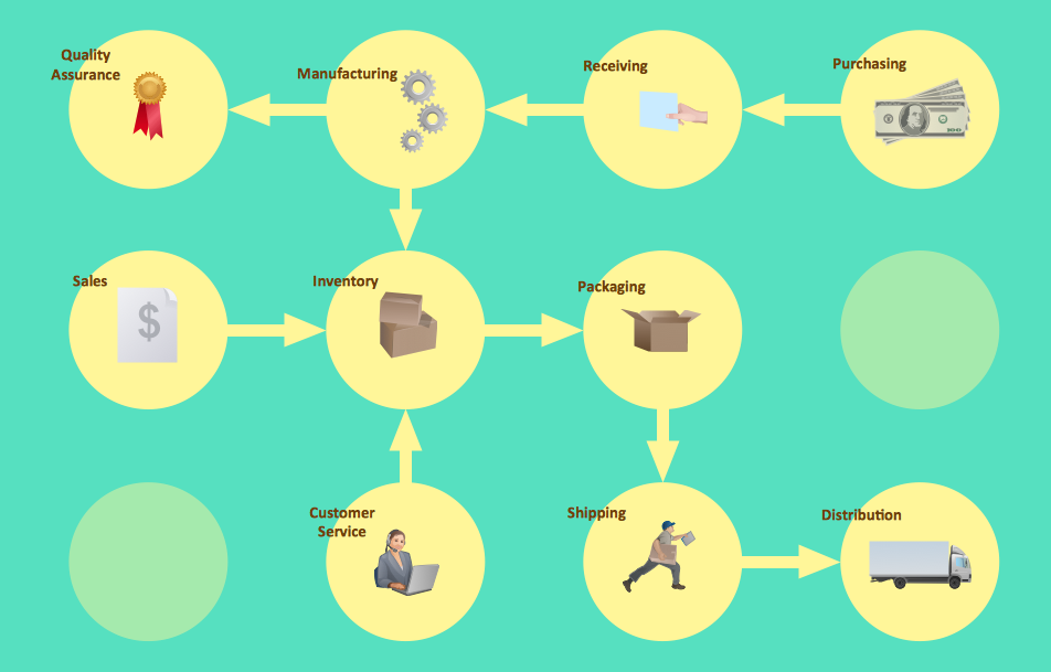
Picture: Business Graphics and Diagramming Package
UML Package Diagram illustrates the functionality of a software system.
ConceptDraw has 393 vector stencils in the 13 libraries that helps you to start using software for designing your own UML Diagrams. You can use the appropriate stencils of UML notation from UML Package library.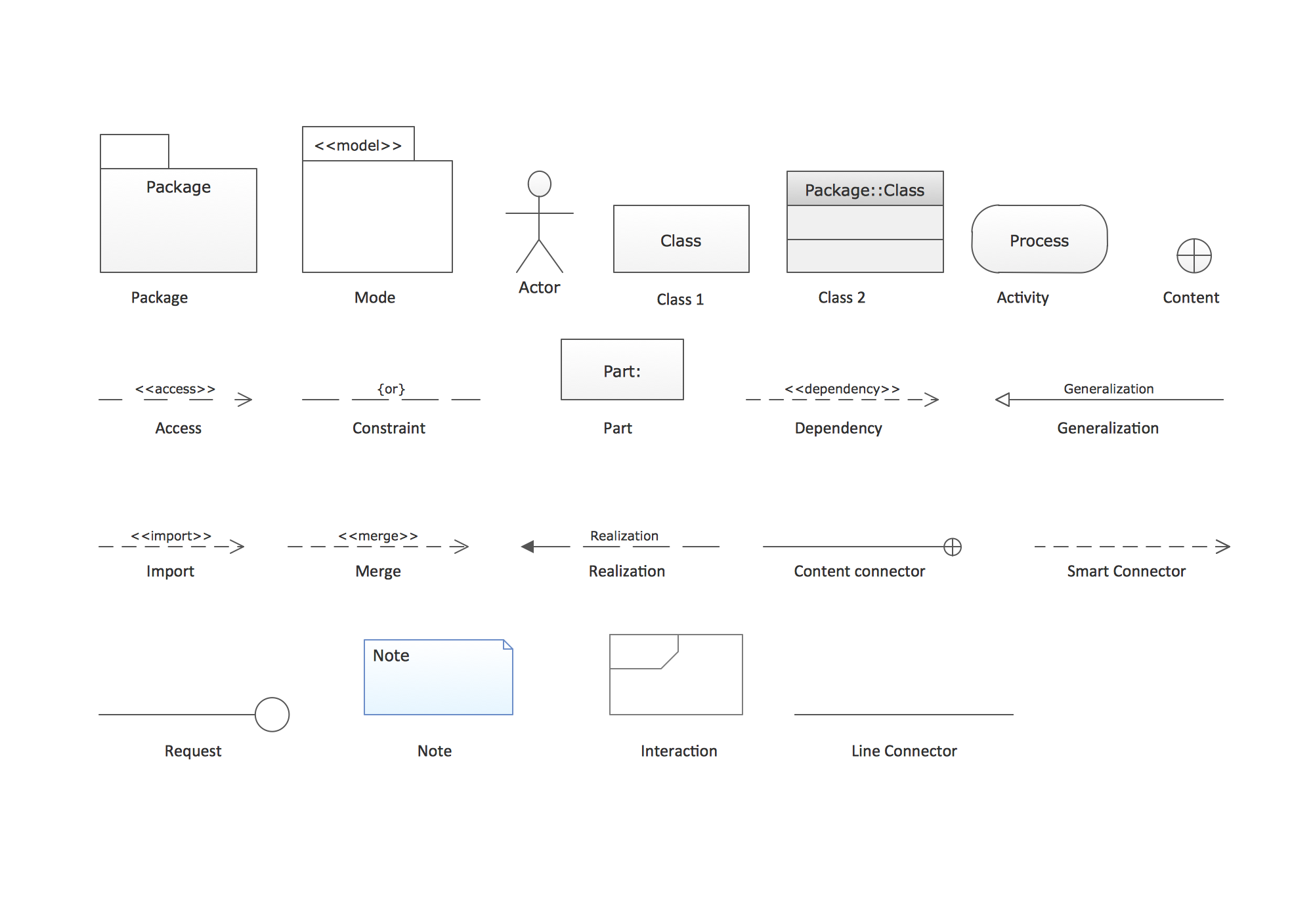
Picture: UML Package Diagram. Design Elements
Related Solution:
This sample was created in ConceptDraw DIAGRAM diagramming and vector drawing software using the UML Class Diagram library of the Rapid UML Solution from the Software Development area of ConceptDraw Solution Park.
This sample describes the use of the classes, the generalization associations between them, the multiplicity of associations and constraints. Provided UML diagram is one of the examples set that are part of Rapid UML solution.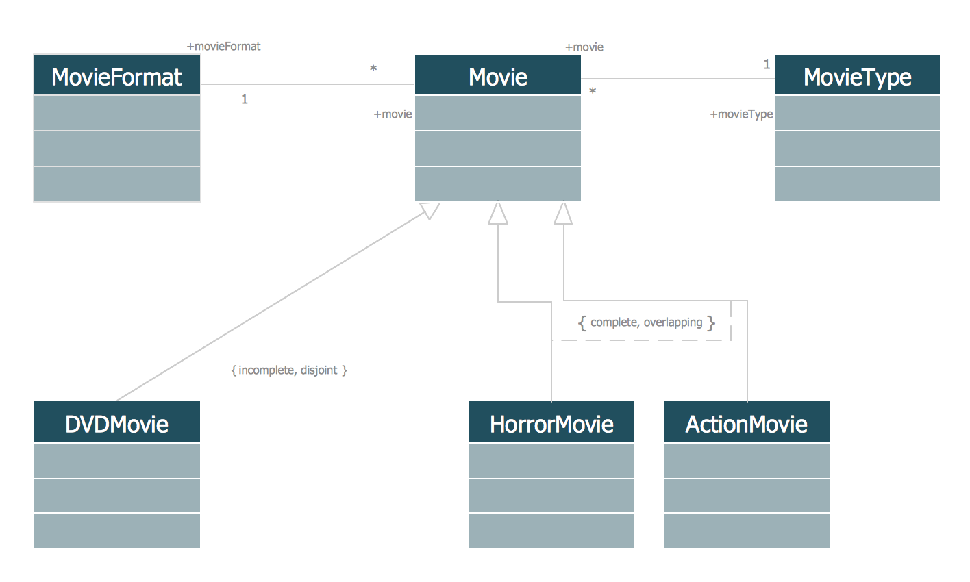
Picture: UML Class Diagram Generalization ExampleUML Diagrams
Related Solution:
Everyone who starts the construction, repair or remodeling of the home, flat or office, is facing with a need of visualization its ideas for visual explanation how all should to be for the foreman and construction team. It is incredibly convenient to use for this professional home architect software. ConceptDraw DIAGRAM software enhanced with Floor Plans solution provides a lot of built-in drawing tools which allow you quick and easy create design plans for the home of your dreams.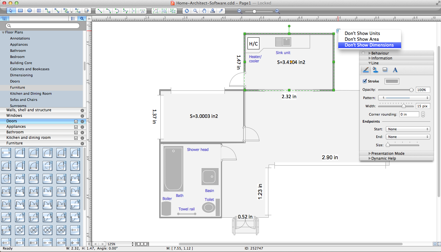
Picture: Home Architect Software. Home Plan Examples
Related Solution:
ConceptDraw
DIAGRAM 18