Unified Modeling Language Diagram
Unified Modeling Language (UML) is an open standard that uses graphic notations for creating visual models of object-oriented software systems.
UML is a language of graphic description for object modeling in the field of software engineering. It was created for definition, visualization, designing of software systems.
There are 13 types of UML diagrams. Rapid UML Solution from the Software Development area of ConceptDraw Solution Park provides templates, samples and libraries with vector objects to help you create the UML diagram of any type quick, easy and effective.
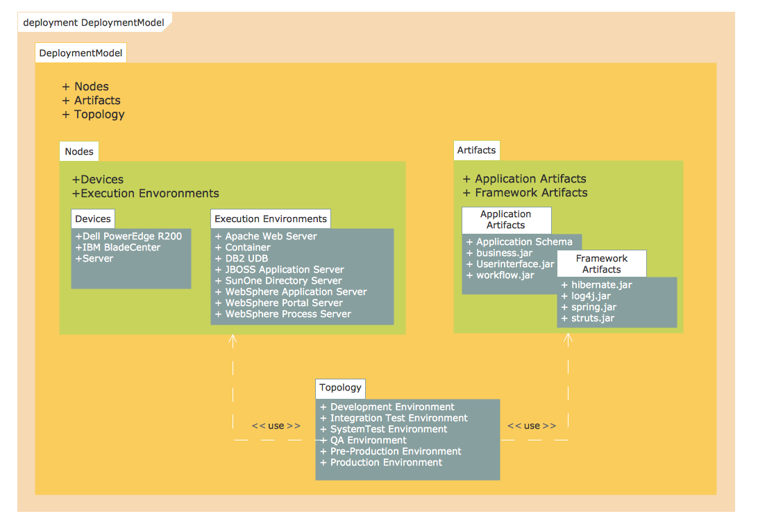
Pic. 1. Unified Modeling Language Diagram - Deployment Model Structure.
This sample was created in ConceptDraw DIAGRAM diagramming and vector drawing software using the UML Package Diagram library of the Rapid UML Solution. It shows the UML Package Diagram that contains nodes and artifacts.
The UML diagrams produced with ConceptDraw DIAGRAM are vector graphic documents and are available for reviewing, modifying, and converting to a variety of formats (image, HTML, PDF file, MS PowerPoint Presentation, Adobe Flash or MS Visio).
THREE RELATED HOW TO's:
Unified Modeling Language (UML) is a language of graphic description for object modeling in the field of software engineering. UML was created for definition, visualization, designing of software systems. UML is an open standard that uses graphic notations for creating visual models of object-oriented software systems.
The Rapid UML Solution for ConceptDraw DIAGRAM presentsthe intuitive RapidDraw interface that helps you to make the UML Diagram of any of these 13 types quick and easy.
Picture: UML Software
Related Solution:
While developing software, it is very important to have a visual model, because it helps to represent the logic and the architecture of an application. Experienced engineers use UML diagrams to denote relationships between classes and their instances. UML is a general language for a set of diagrams like deployment diagrams, object diagrams or use case diagrams.
This diagram represents UML class diagram used for a software system development using an object-oriented method. Class diagrams are categorized as static structure diagrams that depict the physical structure of a system. Class diagram divides a software system's structure into "classes". Classes are defined by the methods and variables of objects. UML Class diagram is used to depict relationships and source code dependencies between objects.
Picture: UML Diagram
Related Solution:
Two types of diagrams are used in UML: Structure Diagrams and Behavior Diagrams. Behavior Diagrams represent the processes proceeding in a modeled environment. Structure Diagrams represent the elements that compose the system.
Picture: UML Diagram Types List
Related Solution: