Vacuum Tube
The vacuum tube, electron tube, or valve is a glass tube with removed gas and vacuum created. It includes two or more electrodes to control electron flow: a heated filament (cathode) and a positively charged plate (anode). The filament is heated by an electrical current from the power supply unit and emits a steady flow of electrons. This phenomenon is called a thermionic emission and originally was known as the Edison effect. In turn, the plate attracts the emitted electrons. The electrons flow only in one direction through the vacuum tube - from the cathode to the positive anode and are attracted to it. They cannot flow in the reverse direction because the plate is not heated and does not emit electrons. At the same time, the filament has a dual function: in addition to emitting electrons when heated, it creates an electric field due to the potential difference. The device may also include other details like the additional grids. They are installed within the tube and control the current between the cathode and anode. These grids are the sparse elements through which electrons pass to the plate.
The vacuum tubes allow amplifying the electric signals by controlling the rate of electron flow and the charge on the intervening grid. The vacuum tube with only two electrodes is called a diode and is used for rectification. It converts alternating current (AC) to pulsating direct current (DC). Depending on the number of additional grids the tube is called a triode, tetrode, pentode, etc. The triode has three electrodes, the tetrode has respectively four electrodes, and so on.
The vacuum tubes were developed by John Ambrose Fleming in 1904 based on the Edison effect that electricity can move through gas or vacuum, not necessarily through a solid material. The vacuum tubes allowed switching on and off the flow of electrons. They were crucial to the development of radio and telephone systems, televisions, radar equipment, and the first computers as switches, amplifiers, or instead of mechanical relays.
However, the lifetime of most vacuum tubes is limited by the filament or heater burning out. Therefore they are installed as replaceable units and aren't popular currently. The lifetime of the vacuum tube depends on the cathode temperature, the purity of the material it is made on, and the degree of vacuum in the tube.
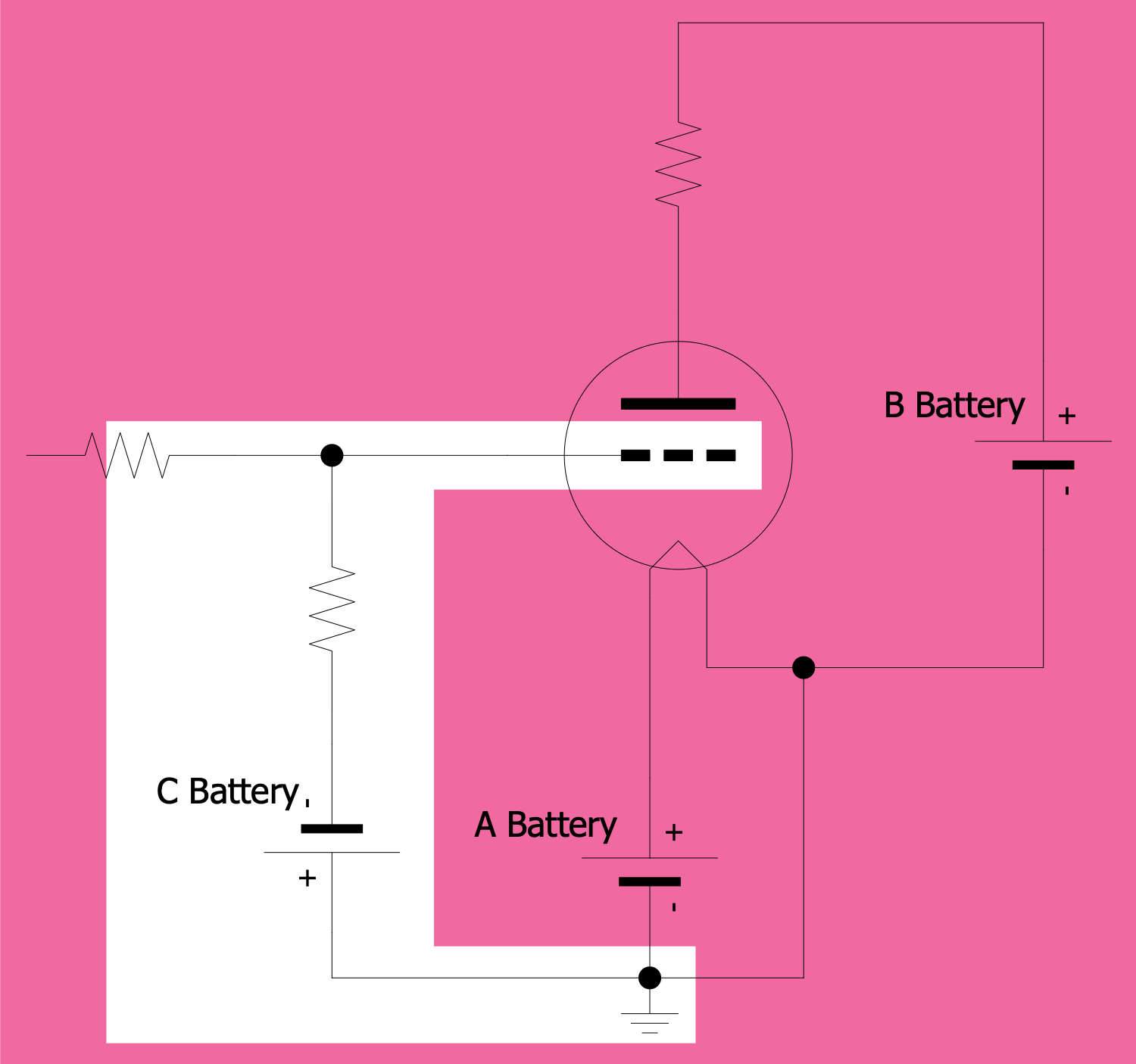
Example 1. Battery Circuit of a Triode Vacuum Tube
Nowadays, vacuum tubes are used primarily in high-end audio equipment, electric guitars, vacuum fluorescent displays, systems that need a high-frequency operation, high-power output, or very high amplification like X-ray machines, radars, magnetrons for microwave ovens. In all other equipment, the transistors are used.
The invention of transistors in the 1950s allowed replacing of vacuum tubes due to their smaller size, better efficiency, reliability, durability, safety, cheaper cost, less fragile, longer lifetime, and ability to operate on lower voltages and using less power. Since the invention of transistors, most radios, television sets, and amplifiers began to use them.
However, due to the latest research, vacuum tubes have a new life. In the last decades, engineers created a nano-sized version of a vacuum tube that is even faster and hardier than a transistor and is also radiation-proof.
ConceptDraw DIAGRAM software offers the Electron Tube Circuits solution with a collection of vector stencil libraries and samples which will effectively and professionally help you to create a vacuum tube, gas-filled tube, or electron tube circuit in minutes.

Example 2. Vacuum Tubes Library Design Elements

Example 3. Vacuum Tubes IEC Library Design Elements

Example 4. Photomultiplier Voltage Divider Circuit
The Electron Tube Circuits samples you see on this page were created in ConceptDraw DIAGRAM software using the drawing tools of the Electron Tube Circuits Solution. These examples successfully demonstrate the solution's capabilities and professional results you can achieve using it. An experienced user spent 5-10 minutes creating each of these samples.
Use the drawing tools of the Electron Tube Circuits solution to design your own Electron Tube Circuits Infographics quick, easy, and effective.
All source documents are vector graphic documents. They are available for reviewing, modifying, or converting to a variety of formats (PDF file, MS PowerPoint, MS Visio, and many other graphic formats) from the ConceptDraw STORE. The Electron Tube Circuits Solution is available for ConceptDraw DIAGRAM users.