Made with
ConceptDraw
DIAGRAM 18

Visio Files and ConceptDraw

Knowing MS Visio as a great vector graphics and diagramming application, which is nowadays a part of the Microsoft Office family, you might still find ConceptDraw DIAGRAM a better tool for drawing your own great looking schemes, diagrams, flowcharts and charts, as well as map, as the last mentioned software is extended with so many solutions, full of stencil libraries with lots of different design elements and pre-made examples, which all can be used for making the professionally looking drawings within a short period of time (sometimes even a few minutes are enough to complete a simple chart or map, having the pre-made template as a draft).

MS Visio application was developed by the “Shapeware Corporation”, renamed in 1995 changing its name to “Visio Corporation”, being acquired by “Microsoft Corporation” in 2000. There were two editions of “Visio 2013” for Windows, one of which was “Standard” and another — “Professional”. Both of them share the same interface, but the difference is in that the last one has a few templates available, while ConceptDraw DIAGRAM provides lots and lots of examples and samples for its users to simplify their work with creating any needed drawings of any complexity.

After Visio 2013 was introduced, “Microsoft Corporation” changed the native file format used in earlier versions of Microsoft Visio, based on a new XML file structure that was highly compressed. The implementation of the mentioned file structure changes improved the customer experience and, as a result, it is now possible to use an alternative to MS Visio, having the files created in Visio to edit while working in ConceptDraw DIAGRAM software, as ConceptDraw DIAGRAM is a great and viable alternative for both individuals and organizations which are looking for a professional business solution.


Visio Exchange

Pic 2. Import Visio File

ConceptDraw DIAGRAM can import and export any file created in MS Visio to work with it, in case it is a Visio VSDX file format. There are many more advantages of using ConceptDraw DIAGRAM diagramming software as it is simple in use, as well as economical application, which allows to save both time and money providing the existing, previously created templates, such as those mentioned in the solutions from ConceptDraw STORE application as well as from this site. To open any Visio file, such as “.vsdx”, in ConceptDraw, you can simply place the document in the better and more useful software — ConceptDraw DIAGRAM — to start editing it and so to finish with it within only a few hours or even minutes, depending on how familiar and good you are with ConceptDraw DIAGRAM

Opening Visio Files in ConceptDraw


The native file format for Visio files is .vsdx, which can be opened by ConceptDraw DIAGRAM When opening MS Visio .vsdx extension file with ConceptDraw DIAGRAM there you may notice some differences when viewing the file in MS Visio and ConceptDraw DIAGRAM

ConceptDraw DIAGRAM does not support footers and headers, so any footer and header information that was in the MS Visio file will not be displayed in ConceptDraw DIAGRAM The header and footer information is not lost; they are just not viewable or modifiable within ConceptDraw DIAGRAM

Some MS Visio fonts are not supported by ConceptDraw. If this is the case, then you may select from a list of available fonts supported by ConceptDraw DIAGRAM when prompted.

Importing and Exporting MS Visio and ConceptDraw DIAGRAM Files

  1. To Import MS Visio Files to ConceptDraw DIAGRAM

    1. From the ConceptDraw DIAGRAM File menu, select Import.
    2. Select MS Visio VSDX.
    3. From the Open window, select the desired MS Visio file to be imported. Click Ok.

  2. To Export ConceptDraw DIAGRAM files to MS Visio:


    1. From the File menu, select Export.
    2. Select MS Visio VSDX.
    3. From the Open window, select the desired location folder. Click Ok.

Visio Files and ConceptDraw *

Pic 2. Visio Exchange

Visio Exchange

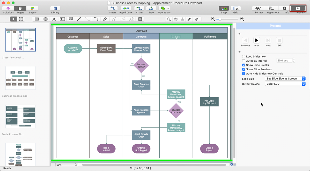
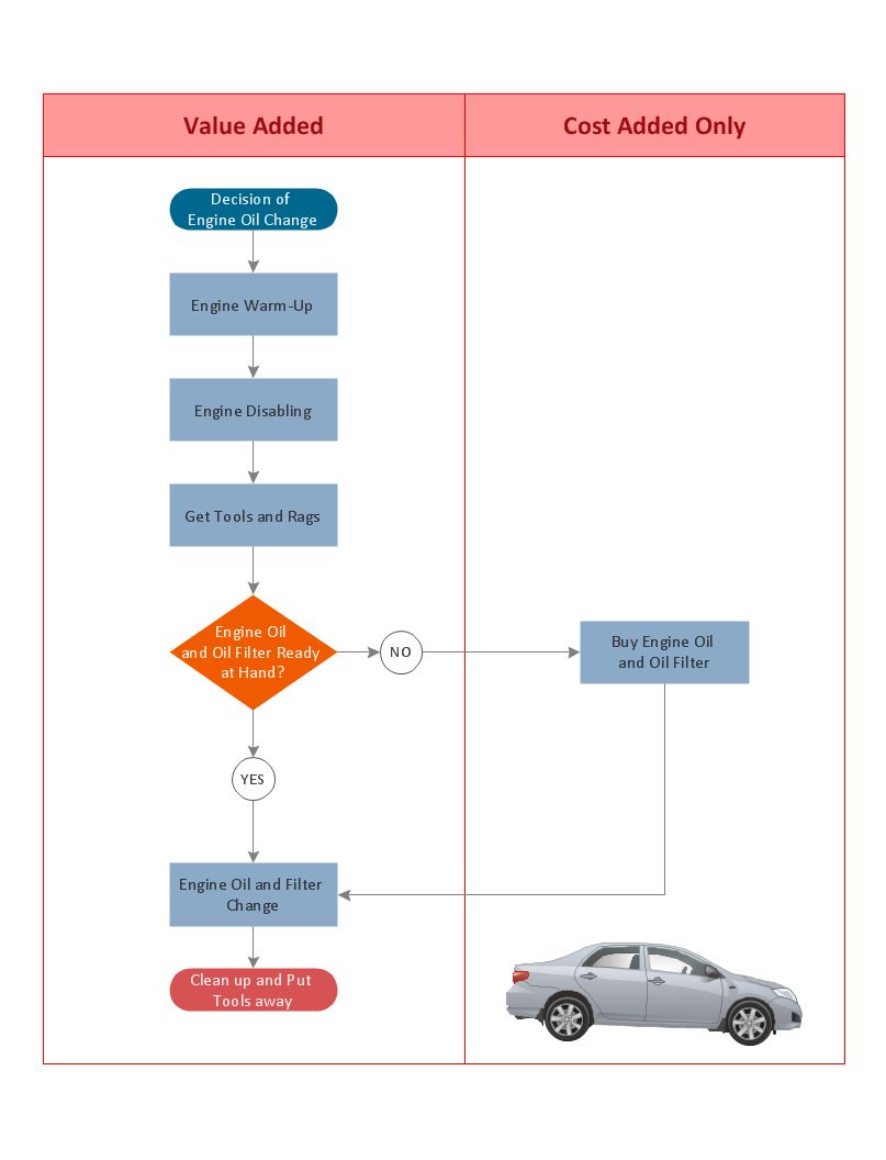
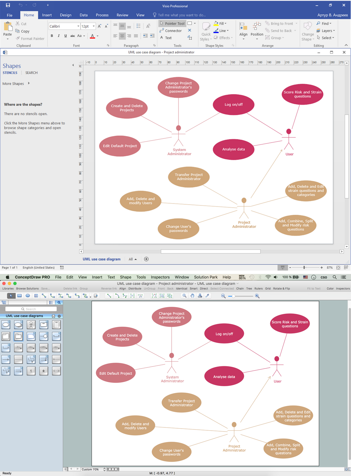
Pic 3. Business Process in Visio

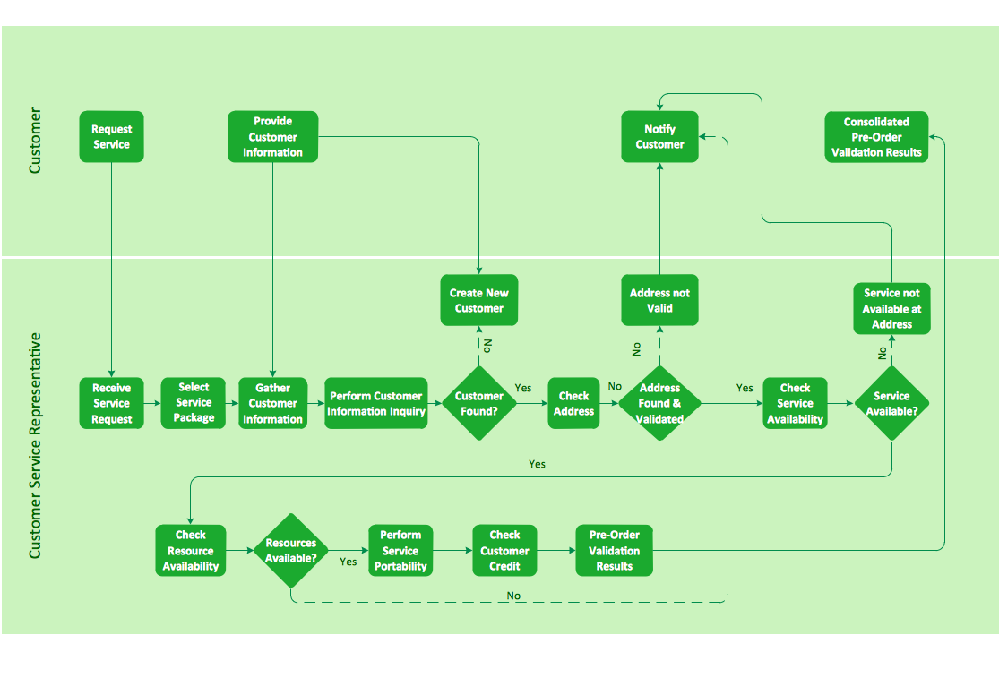
This examples illustrates how MS Visio 2016 diagram (VSDX file format) has been converted into ConceptDraw DIAGRAM diagram.

All source documents are vector graphic documents. They are available for reviewing, modifying, or converting to a variety of formats (PDF file, MS PowerPoint, MS Visio, and many other graphic formats)


TEN RELATED HOW TO's:
AWS platform is great to develop reliable applications. If you are already aware of all the benefits that Amazon Web Services diagrams bring, then you'll need also a diagramming tool for architecture to share your vision. Luckily, ConceptDraw DIAGRAM has a special AWS Diagrams solution with vector icons and templates that are easy to edit. The AWS architecture diagram, you see on this drawing, was designed using ConceptDraw Amazon Web Services Architecture Diagrams (AWS) solution. The 14 libraries, delivered with this solution introduces near 250 vector graphic images used to draw AWS Diagrams. The AWS Architecture Diagrams solution is a valuable tool for programmers, software architects and other IT professionals. It enables them to develop reliable applications with a high stage of interaction with AWS cloud.Amazon Web Services Diagrams <br>diagramming tool for architecture *
Picture: Amazon Web Services Diagrams diagramming tool for architecture
There are three main types of organizational structures which can be adopted by organizations depending on their objectives: functional structure, divisional structure, matrix structure. ConceptDraw DIAGRAM diagramming and vector drawing software enhanced with 25 Typical Orgcharts solution from the Management area of ConceptDraw Solution Park is ideal for designing diagrams and charts of any organizational structure types.Organizational Structure Types *
Picture: Organizational Structure Types
Related Solution:
IT world is extremely rational and logical. So what can be more precise than Software Diagrams to rate the results of work? Visual statistics is the best way to understand the data. This figure demonstrates the data flow diagram (DFD), which was created to describe the electronic system of custom purchase. This is the process of buying using electronic bar code scanning system. Such systems are used in large stores. The cashier scans the bar code, the system outputs the data on the price of the goods and carries out a purchase process. This DFD utilizes the Gane/Sarson notation. To create it The ConceptDraw DFD solution has been applied.Software Diagrams
Picture: Software Diagrams
Electrical plan is a document that is developed during the first stage of the building design. This scheme is composed of conventional images or symbols of components that operate by means of electric energy. To simplify the creation of these schemes you can use house electrical plan software, which will not require a long additional training to understand how to use it. You only need to install the necessary software ant it’s libraries and you’ll have one less problem during the building projection. Any building contains a number of electrical systems, including switches, fixtures, outlets and other lightening equipment. All these should be depicted in a building electrical plans and included to general building documentation. This home electrical plan displays electrical and telecommunication devices placed to a home floor plan. On the plan, each electrical device is referenced with the proper symbol. Electrical symbols are used for universal recognition of the building plan by different persons who will be working on the construction. Not all possible electric symbols used on a certain plan, so the symbols used in the current home plan are included to a legend. The electrical home plan may be added as a separate document to a complete set of building plans.House Electrical Plan Software
Picture: How To use House Electrical Plan Software
Related Solution:
You want to connecting objects manually? You don't know how should diagramming software work? Is it possible to develop a diagram as quickly as the ideas come to you? Yes. The innovative ConceptDraw Arrows10 Technology - This is more than enough versatility to draw any type of diagram with any degree of complexity. You can start draw your diagram manually now.ConceptDraw Arrows10 Technology *
Picture: ConceptDraw Arrows10 Technology
ConceptDraw DIAGRAM is a powerful diagramming and vector drawing software. Extended with Matrices Solution from the Marketing Area of ConceptDraw Solution Park it became the best software for quick and easy designing various types of Matrix Diagrams, including Positioning Map.Positioning Map *
Picture: Positioning Map
Related Solution:
Using diagrams, you can visualize the flow of the information or build a detailed data structure. There's no need to have a degree in software and database design with ConceptDraw DIAGRAM , because this software has all the tools needed in developing models and diagrams. Project planning, designing and prototyping was never so easy. This UML diagrams can be used to visualize a model of the data base development process. A UML diagram shows a graphical view of a structure of software system: components and relationships. Using Unified Modeling Language helps to depict logical and physical elements of a data base, visually represent requirements and sub-systems. UML diagrams allows developers to organize and predict critical issues, as well as collaborate data base information.Software and Database Design with ConceptDraw DIAGRAM  *
Picture: Software and Database Design with ConceptDraw DIAGRAM
Related Solution:
Unfortunately, a man can’t predict the future and no one is safe from natural disasters, such as floods, earthquakes, hurricanes or fires. Nonetheless, what you can do to ensure safety for you and your relatives is to create an emergency plan, so everyone will know what to do if emergency happens. Keep that plan simple and train it several times a year so that no one could forget any details of it. Fire and emergency plans are important to supply people with a visual safety solution. This diagram presents a set of standard symbols used to depict fire safety, emergency, and associated information. Using clear and standard symbols on fire emergency plans provides the coherence of collective actions , helps to avoid embarrassment, and improves communications in an emergent situation. The fire emergency symbols are intended for the general emergency and fire service, as well as for building plans ,engineering drawings and insurance diagrams. They can be used during fire extinguishing and evacuation operations, as well as trainings. It includes vector symbols for emergency management mapping, emergency evacuation diagrams and plans.Emergency Plan
Picture: Emergency Plan
Related Solution:
There are many tools to manage a process or to illustrate an algorithm or a workflow. Flowcharting is one of those tools. However, it may be difficult to show complex processes that require multiple attributes or several people in a simple flowchart, so a cross-functional flowchart would be a solution for that situation. To create such flowchart, group processes and steps to labeled rows or columns, and divide those groups with horizontal or vertical parallel lines. It is worth mentioning that there are different types of cross-functional flowcharts, like opportunity or deployment flowchart. This diagram shows a cross-functional flowchart that was made for a trading process. It contains 14 processes, distributed through 5 lines depicting the participants who interact with the process. Also there are connectors that show the data flow of information between processes. The cross-functional flowchart displays a detailed model of the trading process, as well as all participants in the process and how they interact with each other. The lines in the flowchart indicates the position, department and role of the trading process participants.Cross-Functional Flowchart
Picture: Cross-Functional Flowchart
Related Solution:
Users can start drawing their own flowchart diagrams in fast and simple way with ConceptDraw software. ConceptDraw DIAGRAM is the only professional diagramming software that works on both Windows and Macintosh platforms. All its documents and libraries are 100% compatible and can be exchanged hassle-free between the platforms.Create a Flow Chart *
Picture: Create a Flow Chart
Related Solution:
ConceptDraw
DIAGRAM 18