Electrical Symbols — Qualifying

The vector stencils library "Qualifying" contains 56 qualifying symbols.
Use these shapes to annotate or specify characteristics of objects in electrical drawings, electronic schematics, circuit diagrams, electromechanical drawings, and wiring diagrams, cabling layout diagrams in the ConceptDraw PRO diagramming and vector drawing software extended with the Electrical Engineering solution from the Engineering area of ConceptDraw Solution Park.
www.conceptdraw.com/ solution-park/ engineering-electrical
Positive polarity

Negative polarity

Neutral symbol

6-phase double delta

Electret

Radiation, non-ion.
Radiation, ion.

Radiation, non-ion., coherent
Radiation, ion., coherent

Radiation, non-ion. 2
Radiation, ion. 2

Radiation, non-ion., coherent 2
Radiation, ion., coherent 2

Multiple-phase

Multiple-phase 2

Multiple-phase, interconnect.

Multiple-phase, interconnect. 2

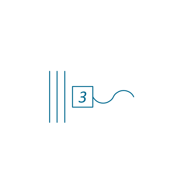
3 separate windings

3 separate windings, interconnect.

3 separate windings, interconnect. 2
3-phase (V)
-qualifying---vector-stencils-library.png--diagram-flowchart-example.png)
3-Phase (T)
-qualifying---vector-stencils-library.png--diagram-flowchart-example.png)
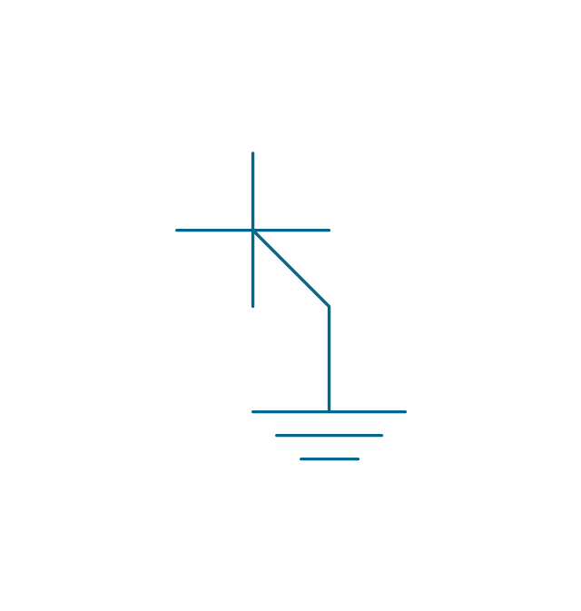
3-phase delta 3

3-phase delta 1

3-phase delta 1, grounded

3-phase delta 2

3-phase delta 2, grounded
3-phase delta 2, grounded 2
3-phase delta 4

3-phase delta 4, grounded

3-phase star, general

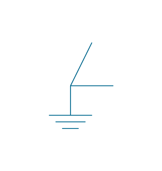
3-phase star, grounded

3-phase star, neutral brought out

3-phase zigzag

3-phase zigzag, grounded

3-phase 4-wire, general

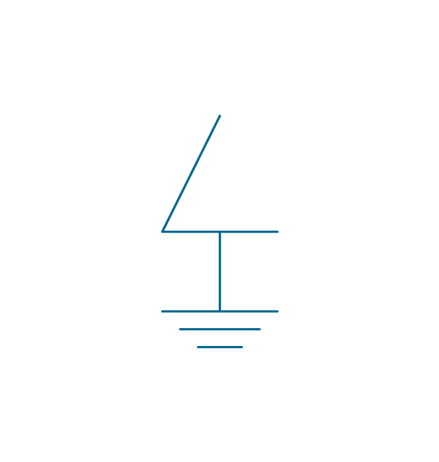
3-phase 4-wire, grounded

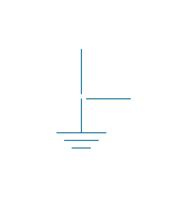
3-phase 4-wire, neutral brought out

2-phase 3-wire

2-phase 3-wire, separated

2-phase 3-wire, grounded

2-phase 3-wire, separat., ground.
2-phase 4-wire

2-phase 4-wire, grounded
4-phase, general

4-phase, grounded

4-phase, neutral brought out

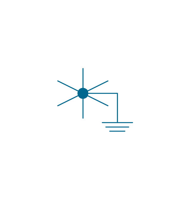
6-phase double star

6-phase double star, grounded

6-phase double star 2

6-phase double star, grounded 2
6-phase polygon

6-phase fork

6-phase fork, neutral

Special connector

Coaxial symbol

 Basic Circuit Diagrams
Basic Circuit Diagrams solution extends the functionality of ConceptDraw DIAGRAM application with a large variety of samples and internationally standardized electrical symbols and electrical circuit diagram symbols including resistor symbol, inductor, amplifier, relay, diode symbol, icons for electrical engineering equipment, electrical circuit instrumentation, active and passive components, digital electronics symbols. Use them to illustrate the electrical circuit of any kind and complexity in minutes, design electrical schematic, wiring diagram, electronic schematics, and more. This solution is effective for electrical engineers, architects, electricians, electrical technicians, builders, interior designers, and many more electricity-related specialists.
Electrical Symbols — Transformers and Windings

Electrical Diagram Symbols F.A.Q.How to Use Electrical ConceptDraw Diagram Software

The vector stencils library "Qualifying" contains 56 qualifying symbols of radiation, polarity, phase, windings, wire, ground, connection, connector, coaxial, electret.
Use these signs to annotate or specify characteristics of objects in electrical drawings, electronic schematics, circuit diagrams, electromechanical drawings, and wiring diagrams, cabling layout diagrams.
"An electrical drawing, is a type of technical drawing that shows information about power, lighting, and communication for an engineering or architectural project. Any electrical working drawing consists of "lines, symbols, dimensions, and notations to accurately convey an engineering's design to the workers, who install the electrical system on the job".
A complete set of working drawings for the average electrical system in large projects usually consists of:
(1) A plot plan showing the building's location and outside electrical wiring.
(2) Floor plans showing the location of electrical systems on every floor.
(3) Power-riser diagrams showing panel boards.
(4) Control wiring diagrams.
(5) Schedules and other information in combination with construction drawings.
Electrical drafters prepare wiring and layout diagrams used by workers who erect, install, and repair electrical equipment and wiring in communication centers, power plants, electrical distribution systems, and buildings." [Electrical drawing. Wikipedia]
The signs example "Design elements - Qualifying" was drawn using the ConceptDraw PRO diagramming and vector drawing software extended with the Electrical Engineering solution from the Engineering area of ConceptDraw Solution Park.
Qualifying symbols

 One-line Diagrams
One-line Diagrams solution is a powerful electrical engineering tool to develop precise and detailed One-line Diagram, Single-line Diagram, Electrical diagram. This solution supplies the ConceptDraw DIAGRAM users with a wide set of vector libraries with special icons and electrical symbol elements for one-line drawing and electrical engineering diagram design including. It includes a large collection of samples of One-line Diagrams illustrating high-voltage and low-voltage systems, different electrical configurations and topologies, transmission systems, application of circuit breakers, protection electrical equipment, etc. It is perfect for all power-related workers, engineers, electricians, and other professionals working in power engineering and energy industries.
Electrical Symbols — Stations

Three-phase Power

Quick Project Start

Football – 2014 FIFA World Cup Standings Group

The vector stencils library "Qualifying" contains 56 qualifying symbols of radiation, polarity, phase, windings, wire, ground, connection, connector, coaxial, electret.
Use these signs to annotate or specify characteristics of objects in electrical drawings, electronic schematics, circuit diagrams, electromechanical drawings, and wiring diagrams, cabling layout diagrams.
"An electrical drawing, is a type of technical drawing that shows information about power, lighting, and communication for an engineering or architectural project. Any electrical working drawing consists of "lines, symbols, dimensions, and notations to accurately convey an engineering's design to the workers, who install the electrical system on the job".
A complete set of working drawings for the average electrical system in large projects usually consists of:
(1) A plot plan showing the building's location and outside electrical wiring.
(2) Floor plans showing the location of electrical systems on every floor.
(3) Power-riser diagrams showing panel boards.
(4) Control wiring diagrams.
(5) Schedules and other information in combination with construction drawings.
Electrical drafters prepare wiring and layout diagrams used by workers who erect, install, and repair electrical equipment and wiring in communication centers, power plants, electrical distribution systems, and buildings." [Electrical drawing. Wikipedia]
The signs example "Design elements - Qualifying" was drawn using the ConceptDraw PRO diagramming and vector drawing software extended with the Electrical Engineering solution from the Engineering area of ConceptDraw Solution Park.
Use these signs to annotate or specify characteristics of objects in electrical drawings, electronic schematics, circuit diagrams, electromechanical drawings, and wiring diagrams, cabling layout diagrams.
"An electrical drawing, is a type of technical drawing that shows information about power, lighting, and communication for an engineering or architectural project. Any electrical working drawing consists of "lines, symbols, dimensions, and notations to accurately convey an engineering's design to the workers, who install the electrical system on the job".
A complete set of working drawings for the average electrical system in large projects usually consists of:
(1) A plot plan showing the building's location and outside electrical wiring.
(2) Floor plans showing the location of electrical systems on every floor.
(3) Power-riser diagrams showing panel boards.
(4) Control wiring diagrams.
(5) Schedules and other information in combination with construction drawings.
Electrical drafters prepare wiring and layout diagrams used by workers who erect, install, and repair electrical equipment and wiring in communication centers, power plants, electrical distribution systems, and buildings." [Electrical drawing. Wikipedia]
The signs example "Design elements - Qualifying" was drawn using the ConceptDraw PRO diagramming and vector drawing software extended with the Electrical Engineering solution from the Engineering area of ConceptDraw Solution Park.
Qualifying symbols
 Home Automation and Wiring
Develop modern solutions for home automation, construct electrical plans and electronic wiring diagrams, design electrical diagram for a smart home system, implement innovations and modern technologies, and describe wiring simply and professionally with ConceptDraw DIAGRAM and Home Automation and Wiring solution. It includes a lot of practical examples of home automation and wiring, and a large collection of vector stencils of home automation equipment, alarm and security equipment, home appliances, electrical symbols, light switches, plugs, sockets, wiring diagram symbols, and more. Home Automation and Wiring solution is the best way to make your home smart still the planning stage and construction of your home electrical schematic.
Process Flowchart


Process Flow Maps

- Qualifying | Design elements - Transmission paths | Symbols Phase
- Electrical Symbols — Qualifying | Qualifying | Symbol For Neutral
- Qualifying - Vector stencils library
- Electrical Symbols — Qualifying | Qualifying | Electrical Neutral Symbol
- Electrical Symbols — Transformers and Windings | Electrical ...
- Electrical Symbols — Rotating Equipment | Qualifying - Vector ...
- Electrical Symbols — Qualifying | Qualifying - Vector stencils library ...
- ConceptDraw Arrows10 Technology | Symbol Of Star Connection
- Electrical Symbols , Electrical Diagram Symbols | Electrical Drawing ...