HelpDesk
How to Create an Electrical Diagram
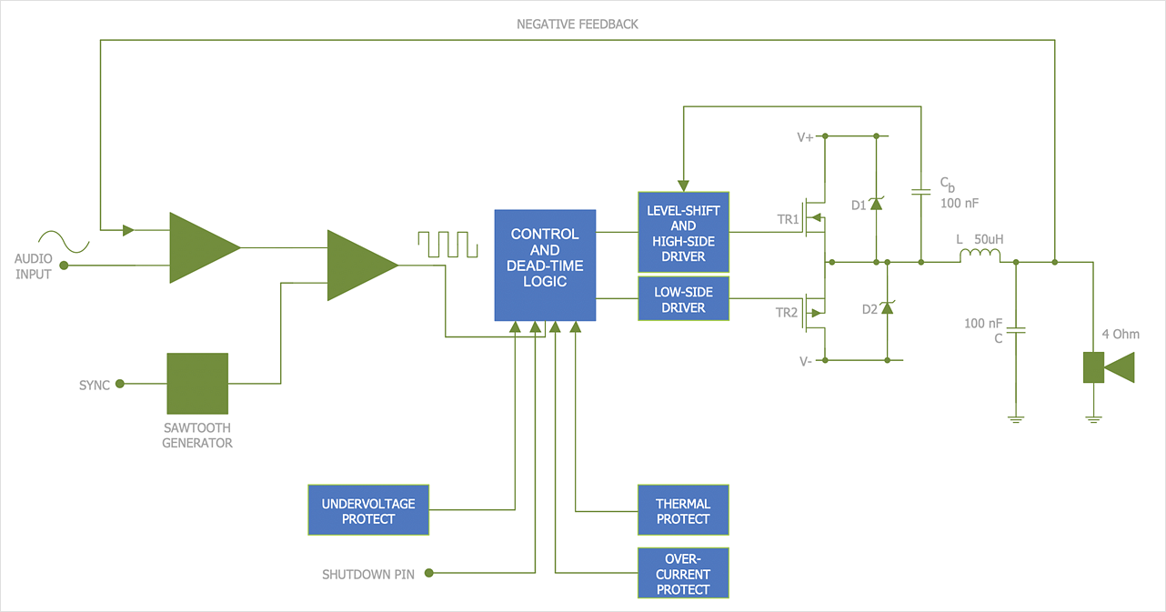
There are many different electric circuit symbols that can be used in a circuit diagram. Knowing how to read circuit diagrams is a useful skill not only for professionals but for any person who can start creating his own small home electronic projects. The circuit diagram shows the scheme of a location of components and connections of the electrical circuit using a set of standard symbols. It can be used for graphical documentation of electrical circuit components. The ability to create electrical diagrams and schematic using ConceptDraw DIAGRAM is delivered by the Electrical Engineering solution. The solution supplied with samples, templates, and libraries of design elements for drawing electrical schematics, digital and analog logic, circuit and wiring schematics and diagrams, power systems diagrams, maintenance and repair diagrams for electronics and electrical engineering.Design Element: Rack Diagram for Network Diagrams
ConceptDraw DIAGRAM is perfect for software designers and software developers who need to draw Rack Diagrams.
ConceptDraw DIAGRAM Compatibility with MS Visio
The powerful diagramming and business graphics tools are now not exception, but the norm for today’s business, which develop in incredibly quick temp. But with the abundance of powerful business diagramming applications it is important to provide their compatibility for effective exchange the information between the colleagues and other people who maybe use different software in their work. During many years Microsoft Visio™ was standard file format for the business and now many people need the visual communication software tools that can read the Visio format files and also export to Visio format. The powerful diagramming and vector drawing software ConceptDraw DIAGRAM is ideal from the point of view of compatibility with MS Visio. Any ConceptDraw DIAGRAM user who have the colleagues that use MS Visio or any who migrates from Visio to ConceptDraw DIAGRAM , will not have any problems. The VSDX (Visio′s open XML file format) and VDX formatted files can be easily imported and exported by ConceptDraw DIAGRAM , you can see video about this possibility.
 Mechanical Engineering
This solution extends ConceptDraw DIAGRAM.9 mechanical drawing software (or later) with samples of mechanical drawing symbols, templates and libraries of design elements, for help when drafting mechanical engineering drawings, or parts, assembly, pneumatic,
- How To use House Electrical Plan Software | Electrical Drawing ...
- Design elements - ERD (crow's foot notation) | Entity Relationship ...
- Entity Relationship Diagram Software Engineering | Design Element ...
- Chemical Engineering Drawing Diagram Software
- Mechanical Engineering | How to Create a Mechanical Diagram ...
- How to Open MS Visio® 2013/ 2016 Files on a Mac® Using ...
- How to Draw a Chemical Process Flow Diagram | Chemical and ...
- How to Draw a Chemical Process Flow Diagram | Engineering ...
- How To Draw A Mechanical Engineering Schematics
- How to Create a Mechanical Diagram | Mechanical Drawing ...
- Mechanical Drawing Symbols | Process Flow Diagram Symbols ...
- Engineering | Technical Drawing Software | Mechanical Drawing ...
- Digital Calendar 2016
- Mechanical Drawing Symbols | Mechanical Design Software ...
- Bubble Diagrams | Entity Relationship Diagram Software ...
- Block Diagram Creator | Block Diagrams | Technical Drawing ...
- Process Flow Diagram Symbols | Technical Drawing Software ...
- Entity Relationship Diagram Software Engineering
- Mechanical Engineering | Mechanical Drawing Symbols | Entity ...
- Mechanical Engineering Drawing Parts

.png)
