"The client–server model of computing is a distributed application structure that partitions tasks or workloads between the providers of a resource or service, called servers, and service requesters, called clients. Often clients and servers communicate over a computer network on separate hardware, but both client and server may reside in the same system. A server host runs one or more server programs which share their resources with clients. A client does not share any of its resources, but requests a server's content or service function. Clients therefore initiate communication sessions with servers which await incoming requests.
Examples of computer applications that use the client–server model are Email, network printing, and the World Wide Web." [Client–server model. Wikipedia]
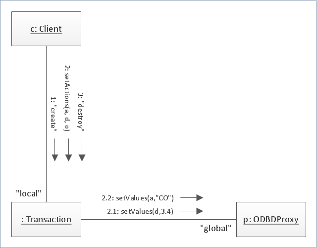
The UML communication diagram example "Client server access" was created using the ConceptDraw PRO diagramming and vector drawing software extended with the Rapid UML solution from the Software Development area of ConceptDraw Solution Park.
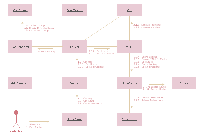
"Communication diagram (called collaboration diagram in UML 1.x) is a kind of UML interaction diagram which shows interactions between objects and/ or parts (represented as lifelines) using sequenced messages in a free-form arrangement.
Communication diagram corresponds (i.e. could be converted to/ from or replaced by) to a simple sequence diagram without structuring mechanisms such as interaction uses and combined fragments. It is also assumed that message overtaking (i.e., the order of the receptions are different from the order of sending of a given set of messages) will not take place or is irrelevant." [uml-diagrams.org/ communication-diagrams.html]
The template "UML communication diagram" for the ConceptDraw PRO diagramming and vector drawing software is included in the Rapid UML solution from the Software Development area of ConceptDraw Solution Park.
www.conceptdraw.com/ solution-park/ software-uml
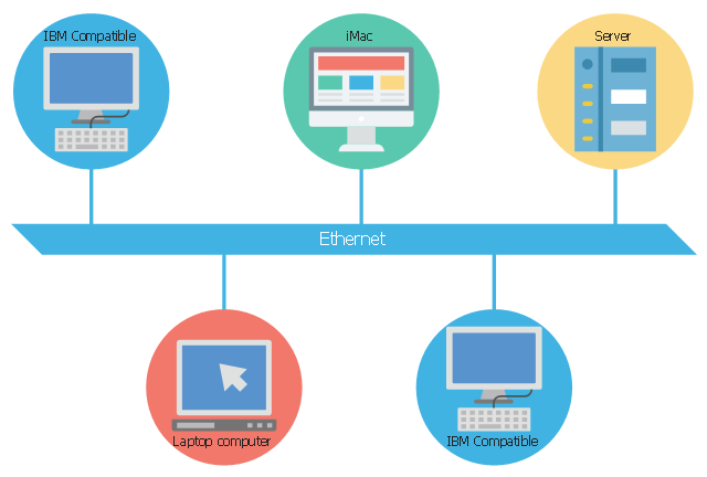
This concept diagram sample shows the local area network using 10BASE5 Ethernet. It was designed on the base of Wikimedia Commons file: Ethernet LAN.svg.
[commons.wikimedia.org/ wiki/ File:Ethernet_ LAN.svg]
This file is licensed under the Creative Commons Attribution-Share Alike 4.0 International license. [creativecommons.org/ licenses/ by-sa/ 4.0/ deed.en]
"A local area network (LAN) is a computer network that interconnects computers within a limited area such as a residence, school, laboratory, university campus or office building and has its network equipment and interconnects locally managed. By contrast, a wide area network (WAN), not only covers a larger geographic distance, but also generally involves leased telecommunication circuits or Internet links.
Ethernet and Wi-Fi are the two most common transmission technologies in use for local area networks." [Local area network. Wikipedia]
The LAN diagram example "Ethernet network" was created using the ConceptDraw PRO diagramming and vector drawing software extended with the Computers and Communications solution from the Illustration area of ConceptDraw Solution Park.
 Business Process Diagrams
Business Process Diagrams solution extends the ConceptDraw PRO BPM software with RapidDraw interface, templates, samples and numerous libraries based on the BPMN 1.2 and BPMN 2.0 standards, which give you the possibility to visualize equally easy simple and complex processes, to design business models, to quickly develop and document in details any business processes on the stages of project’s planning and implementation.
 Computers and Communications
Computers and communications solution extends ConceptDraw PRO software with illustration samples, templates and vector stencils libraries with clip art of computers, control devices, communications, technology, Apple machines.
 Computer Network Diagrams
Computer Network Diagrams solution extends ConceptDraw PRO software with samples, templates and libraries of vector stencils for drawing the computer network topology diagrams.
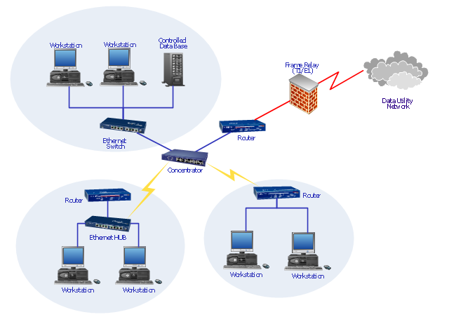
"A computer network or data network is a telecommunications network that allows computers to exchange data. In computer networks, networked computing devices (network nodes) pass data to each other along data connections. The connections (network links) between nodes are established using either cable media or wireless media. The best-known computer network is the Internet.
Network devices that originate, route and terminate the data are called network nodes. Nodes can include hosts such as servers and personal computers, as well as networking hardware. Two devices are said to be networked when a device is able to exchange information with another device." [Computer network. Wikipedia]
This computer communication network diagram example was created using the ConceptDraw PRO diagramming and vector drawing software extended with the Computer and Networks solution from the Computer and Networks area of ConceptDraw Solution Park.
- Mobile satellite communication network diagram ...
- Communication Diagram UML2.0 / Collaboration UML1.x | UML ...
- UML communication diagram template | Diagramming Software for ...
- UML communication diagram - Client server access | Application ...
- Diagramming Software for Design UML Communication Diagrams ...
- Communication Diagram UML2.0 / Collaboration UML1.x | Network ...
- Idea Communication | UML communication diagram - Client server ...
- Diagramming Software for Design UML Communication Diagrams ...
- Communication Diagram UML2.0 / Collaboration UML1.x ...
- Idea Communication | Diagramming Software for Design UML ...
- Entity Relationship Diagram Software Engineering | Communication ...
- Diagramming Software for Design UML Collaboration Diagrams ...
- Mobile satellite communication network diagram
- Timing diagram | UML Collaboration Diagram (UML2.0 ...
- Unified communications diagram
- How to Create Flowcharts for an Accounting Information System ...
- UML Collaboration Diagram . Design Elements | Diagramming ...
- UML Collaboration Diagram (UML2.0) | Diagramming Software for ...
- UML Use Case Diagrams | Rapid UML | Communication Diagram ...
- UML communication diagram - Client server access | UML ...


