Basic Network Diagram
The Basic Network Diagram is an easy and effective way to design and document a simple network, it lets to represent visually and logically how the different network devices and computer equipment can be installed to meet the main business needs. ConceptDraw DIAGRAM software supplied with Computer Network Diagrams solution from the Computer and Networks area of ConceptDraw Solution Park is a perfect tool for drawing the Basic Computer Network diagrams, designs, schematics, and maps, network architectures, topologies, and layouts. Numerous vector libraries of network symbols, icons and components are incredibly helpful for IT and telecom engineers, stakeholders and end-users when designing Basic Network Diagrams, Common Network Diagrams, Common Network Topologies, 10Base-T Star Network Topologies, Bus Topology Diagrams, Communication Network Diagrams, System Designs, Regional Cable Head-End Diagrams, etc. Collection of predesigned samples and templates included to Computer Network Diagrams solution also greatly extends the capabilities of ConceptDraw DIAGRAM users.
"Logical topology, or signal topology, is the arrangement of devices on a computer network and how they communicate with one another. How devices are connected to the network through the actual cables that transmit data, or the physical structure of the network, is called the physical topology. Physical topology defines how the systems are physically connected. It represents the physical layout of the devices on the network. The logical topology defines how the systems communicate across the physical topologies.
Logical topologies are bound to network protocols and describe how data is moved across the network. ...
EXAMPLE : twisted pair Ethernet is a logical bus topology in a physical star topology layout. while IBM's token ring is a logical ring topology, it is physically set up in star topology." [Logical topology. Wikipedia]
This Cisco logical computer network diagram example was created using the ConceptDraw PRO diagramming and vector drawing software extended with the Cisco Network Diagrams solution from the Computer and Networks area of ConceptDraw Solution Park.
HelpDesk
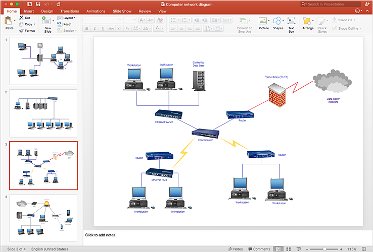
How To Add a Computer Network Diagram to a PowerPoint Presentation
The PowerPoint presentation of a computer network can be very informative. ConceptDraw DIAGRAM allows you to easily create computer network diagrams and then make a PowerPoint Presentation from your network diagrams in a single click."Network topology is the arrangement of the various elements (links, nodes, etc.) of a computer network. Essentially, it is the topological structure of a network, and may be depicted physically or logically. Physical topology refers to the placement of the network's various components, including device location and cable installation, while logical topology shows how data flows within a network, regardless of its physical design. Distances between nodes, physical interconnections, transmission rates, and/ or signal types may differ between two networks, yet their topologies may be identical. The study of network topology recognizes eight basic topologies: Point-to-point, Bus, Star, Ring or circular, Mesh, Tree, Hybrid, Daisy chain." [Network topology. Wikipedia]
The computer network topologies diagram example was created using the ConceptDraw PRO diagramming and vector drawing software extended with the Computer and Networks solution from the Computer and Networks area of ConceptDraw Solution Park.
The computer network topologies diagram example was created using the ConceptDraw PRO diagramming and vector drawing software extended with the Computer and Networks solution from the Computer and Networks area of ConceptDraw Solution Park.
- Network Topologies | Fully Connected Network Topology Diagram ...
- Network Diagram Examples | Bus network topology diagram | Basic ...
- Network Topology | Basic Network Diagram | Network Diagram ...
- Fully Connected Network Topology Diagram | Network Topologies ...
- Tree Network Topology Diagram | Network Topologies | Star ...
- Network Topology | Basic Network Diagram | Daisy Chain Network ...
- Network Diagram Examples
- Network Topology | Basic Network Diagram | Network Diagram ...
- Network Topology | Network Diagram Software | Visio Look a Like ...
- Basic Network Diagram | Visio Look a Like Diagrams | Network ...
- Wireless Network Topology | Hotel Network Topology Diagram ...
- Bus network topology diagram | Network Diagram Examples ...
- Logical network topology diagram | Network Topologies | Network ...
- Complete Network Topology | Fully Connected Network Topology ...
- Network Diagram Examples | Bus network topology diagram ...
- Interactive Voice Response Network Diagram | Cisco Network ...
- Basic Network Diagram | Design Element: Basic Network for ...
- Star Network Topology | Network Topologies | 10Base-T star ...
- Network Topologies | Ring Network Topology | Fully Connected ...


