Star Network Topology


Campus Area Networks (CAN). Computer and Network Examples
. <br>Computer and Network Examples *")

Mesh Network Topology Diagram

Cisco Routers. Cisco icons, shapes, stencils and symbols

Metropolitan area networks (MAN). Computer and Network Examples
. Computer and Network Examples")
 Computer Network Diagrams
Computer Network Diagrams solution extends ConceptDraw DIAGRAM software with samples, templates and libraries of vector icons and objects of computer network devices and network components to help you create professional-looking Computer Network Diagrams, to plan simple home networks and complex computer network configurations for large buildings, to represent their schemes in a comprehensible graphical view, to document computer networks configurations, to depict the interactions between network's components, the used protocols and topologies, to represent physical and logical network structures, to compare visually different topologies and to depict their combinations, to represent in details the network structure with help of schemes, to study and analyze the network configurations, to communicate effectively to engineers, stakeholders and end-users, to track network working and troubleshoot, if necessary.
 Network Layout Floor Plans
Network Layout Floor Plans solution extends ConceptDraw DIAGRAM software functionality with powerful tools for quick and efficient documentation the network equipment and displaying its location on the professionally designed Network Layout Floor Plans. Never before creation of Network Layout Floor Plans, Network Communication Plans, Network Topologies Plans and Network Topology Maps was not so easy, convenient and fast as with predesigned templates, samples, examples and comprehensive set of vector design elements included to the Network Layout Floor Plans solution. All listed types of plans will be a good support for the future correct cabling and installation of network equipment.
Calculate the cost of creating or updating a wireless computer network

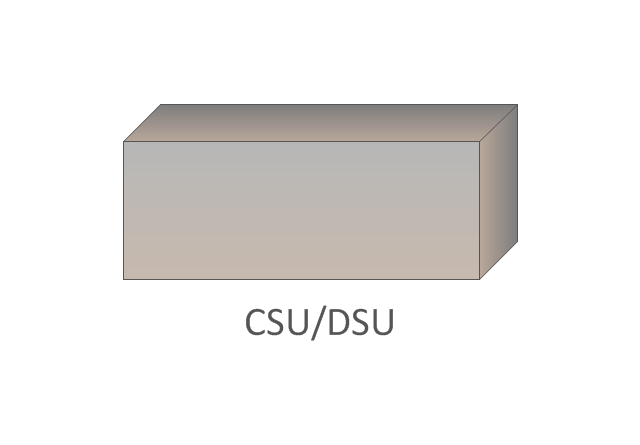
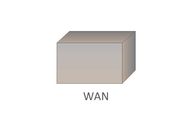
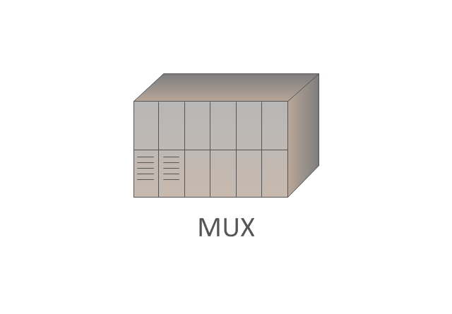
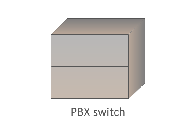
The vector stencils library "Cisco WAN" contains 15 symbols of wide area network (WAN) devices and equipment for drawing Cisco WAN diagrams.
"A wide area network (WAN) is a network that covers a broad area (i.e., any telecommunications network that links across metropolitan, regional, or national boundaries) using leased telecommunication lines. Business and government entities utilize WANs to relay data among employees, clients, buyers, and suppliers from various geographical locations. ...
Related terms for other types of networks are personal area networks (PANs), local area networks (LANs), campus area networks (CANs), or metropolitan area networks (MANs) which are usually limited to a room, building, campus or specific metropolitan area (e.g., a city) respectively.
... it may be best to view WANs as computer networking technologies used to transmit data over long distances, and between different LANs, MANs and other localised computer networking architectures. ...
WANs are often built using leased lines. At each end of the leased line, a router connects the LAN on one side with a second router within the LAN on the other. Leased lines can be very expensive. Instead of using leased lines, WANs can also be built using less costly circuit switching or packet switching methods. Network protocols including TCP/ IP deliver transport and addressing functions. Protocols including Packet over SONET/ SDH, MPLS, ATM and Frame relay are often used by service providers to deliver the links that are used in WANs." [Wide area network. Wikipedia]
The symbols example "Cisco WAN - Vector stencils library" was created using the ConceptDraw PRO diagramming and vector drawing software extended with the Cisco Network Diagrams solution from the Computer and Networks area of ConceptDraw Solution Park.
www.conceptdraw.com/ solution-park/ computer-networks-cisco
CSU/DSU
WAN
MUX
PBX switch
Hub
Hub, blue
NAT

Network cloud, dark
Network cloud, gold
Network cloud, white
Network cloud, standard color
Distributed director
Local director
PBX
DPT
Concept Maps

Draw Network Diagram based on Templates and Examples

Electrical Symbols — Switches and Relays

Cisco Network Objects in ConceptDraw DIAGRAM

Electrical Symbols, Electrical Diagram Symbols

Design Element: Active Directory for Network Diagrams

Interior Design. Office Layout Plan Design Element


Examples of Flowcharts, Org Charts and More


 Wireless Networks
The Wireless Networks Solution extends ConceptDraw DIAGRAM software with professional diagramming tools, set of wireless network diagram templates and samples, comprehensive library of wireless communications and WLAN objects to help network engineers and designers efficiently design and create Wireless network diagrams that illustrate wireless networks of any speed and complexity, and help to identify all required equipment for construction and updating wireless networks, and calculating their costs.
Cisco Buildings. Cisco icons, shapes, stencils and symbols

Pyramid Diagram

- Wide area network (WAN) topology . Computer and Network ...
- Wide area network (WAN) topology . Computer and Network ...
- Frame relay | Cisco WAN - Vector stencils library | Logical symbols ...
- Metropolitan area networks (MAN). Computer and Network Examples
- Campus Area Networks (CAN). Computer and Network Examples ...
- Cisco Switches and Hubs. Cisco icons, shapes, stencils and ...
- Wide area network (WAN) topology . Computer and Network Examples
- Mesh Network Topology Diagram | Mesh Network . Computer and ...
- Logical symbols - Vector stencils library | Cisco WAN - Vector ...
- Multiprotocol Label Switching (MPLS).
- Campus Area Networks (CAN). Computer and Network Examples ...
- Computers and network isometric - Vector stencils library | Cisco ...
- Cisco WAN - Vector stencils library | Active Directory Sites and ...
- Local area network (LAN). Computer and Network Examples ...
- Switches and relays - Vector stencils library | Design elements ...
- Cisco WAN. Cisco icons, shapes, stencils and symbols | Wide area ...
- Computer Network Diagrams | Local area network (LAN). Computer ...
- Cisco optical - Vector stencils library | Logical symbols - Vector ...
- Cisco Routers. Cisco icons, shapes, stencils and symbols | Logical ...
- Wide area network (WAN) topology . Computer and Network ...