Entity Relationship Diagram Symbols

UML Activity Diagram

Draw Fishbone Diagram on MAC Software

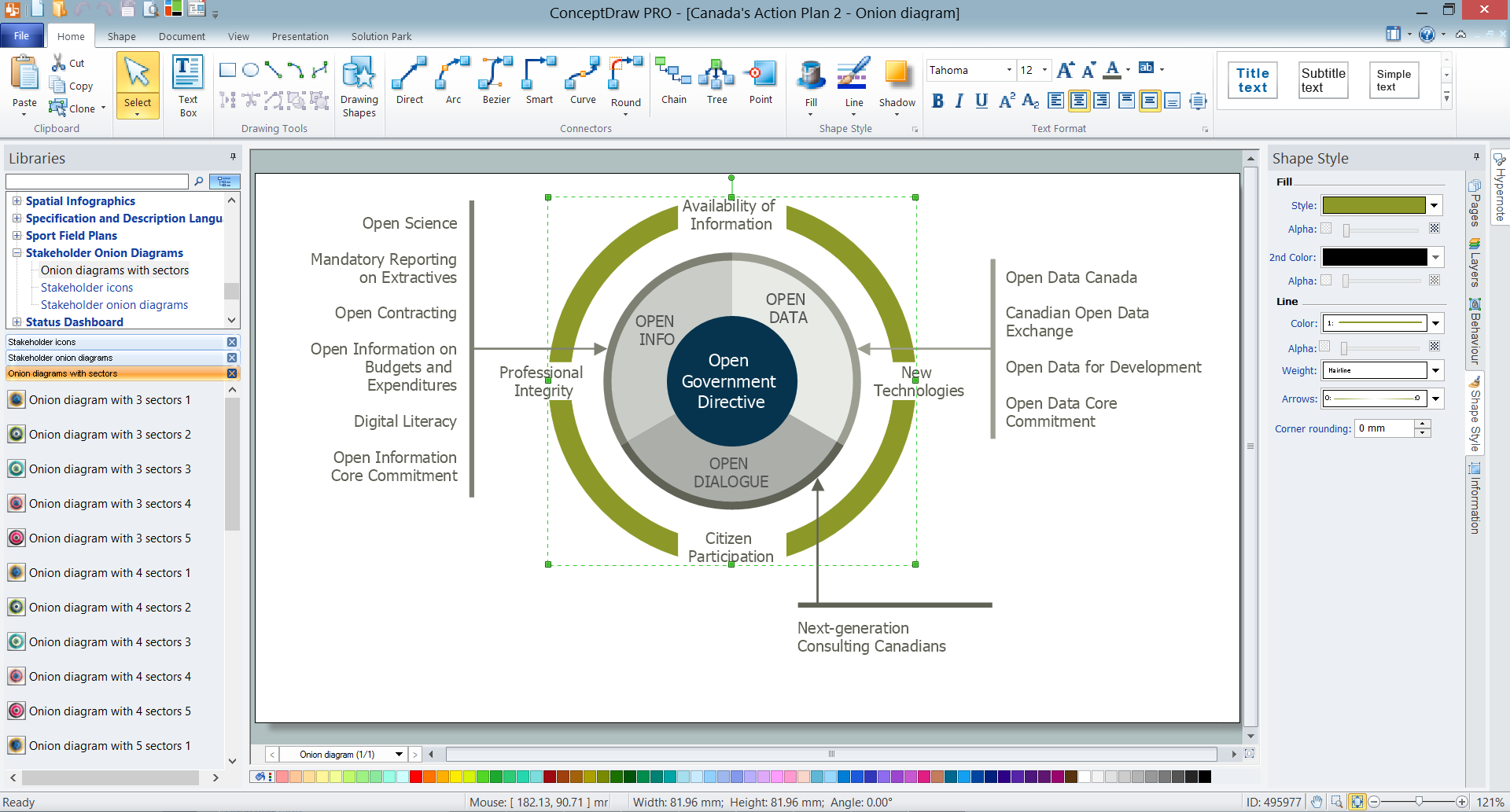
Onion Diagram Templates
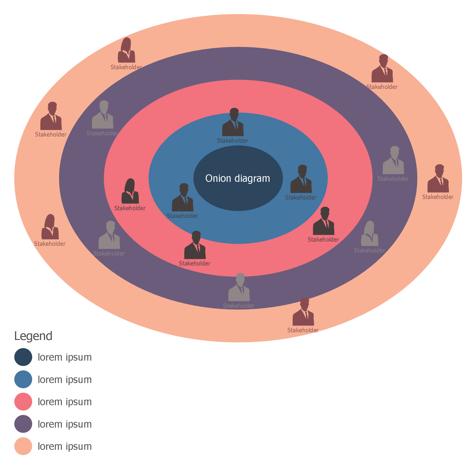
How To Create Onion Diagram
Context Diagram Template

This template shows the Context Diagram. It was created in ConceptDraw DIAGRAM diagramming and vector drawing software using the Block Diagrams Solution from the “Diagrams” area of ConceptDraw Solution Park. The context diagram graphically identifies the system. external factors, and relations between them. It’s a high level view of the system. The context diagrams are widely used in software engineering and systems engineering for designing the systems that process the information.
Bank UML Diagram

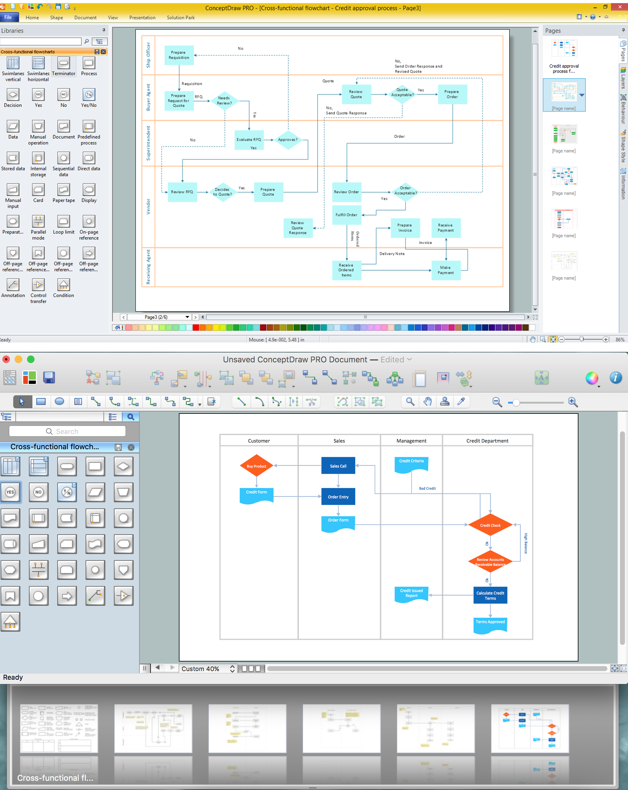
Cross-Functional Flowchart

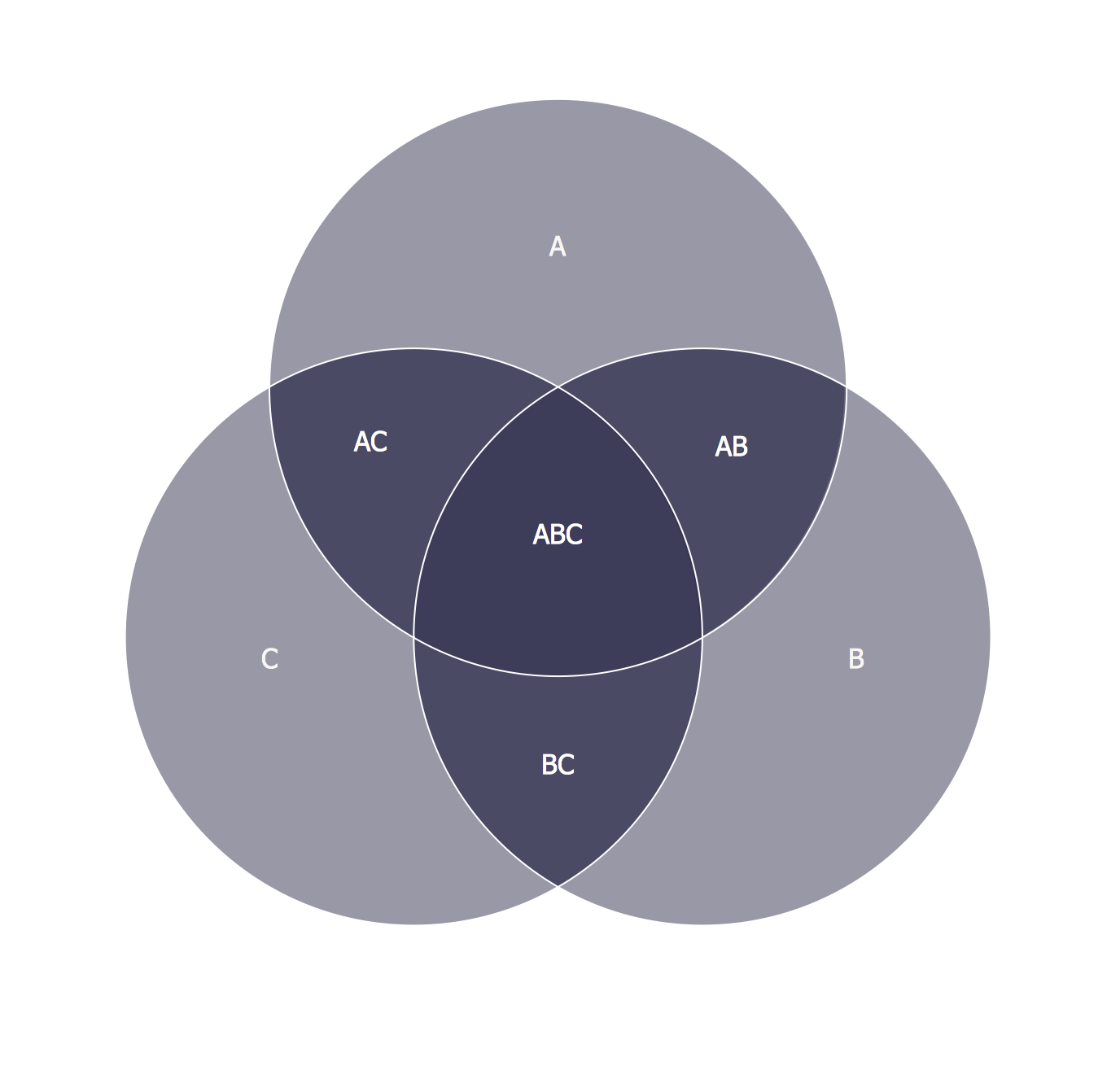
3 Circle Venn Diagram. Venn Diagram Example
UML Flowchart Symbols

- Activity Relationship Chart Template Excel
- Entity-Relationship Diagram (ERD) | Activity Relationship Diagram ...
- Activity Relationship Chart Template Download
- Activity Relationship Chart Excel
- Activity Relationship Chart Software
- Activity Relationship Chart Maker
- Relationship Diagram Template
- Relationship Matrix Template Excel
- Efficiency Format Excel
- How To Make Warehouse Layout In Excel