Graphical Symbols to use in EPC diagrams
Event-Driven Process Chain Diagrams for improvement throughout an organisation. ConceptDraw DIAGRAM - software that reduces the time needed to create a business process model.SDL — Systems Engineering
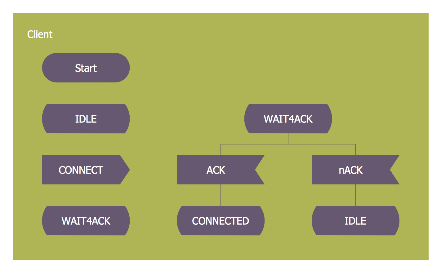
How to design SDL Diagram fast and easy? ConceptDraw DIAGRAM diagramming and vector drawing software supplied with unique Specification and Description Language (SDL) Solution from the Industrial Engineering Area of ConceptDraw Solution Park will help you design SDL Diagram of any complexity without effortsWhat Is a Concept Map
What is a Concept Map and what software is effective for its design? A concept map or conceptual diagram is a diagram that depicts suggested relationships between concepts. As for effective software - we suggest you to pay attention for the ConceptDraw DIAGRAM diagramming and vector drawing software. Extended with Concept Maps Solution from the "Diagrams" Area it is a real godsend for you.Mechanical Drawing Software
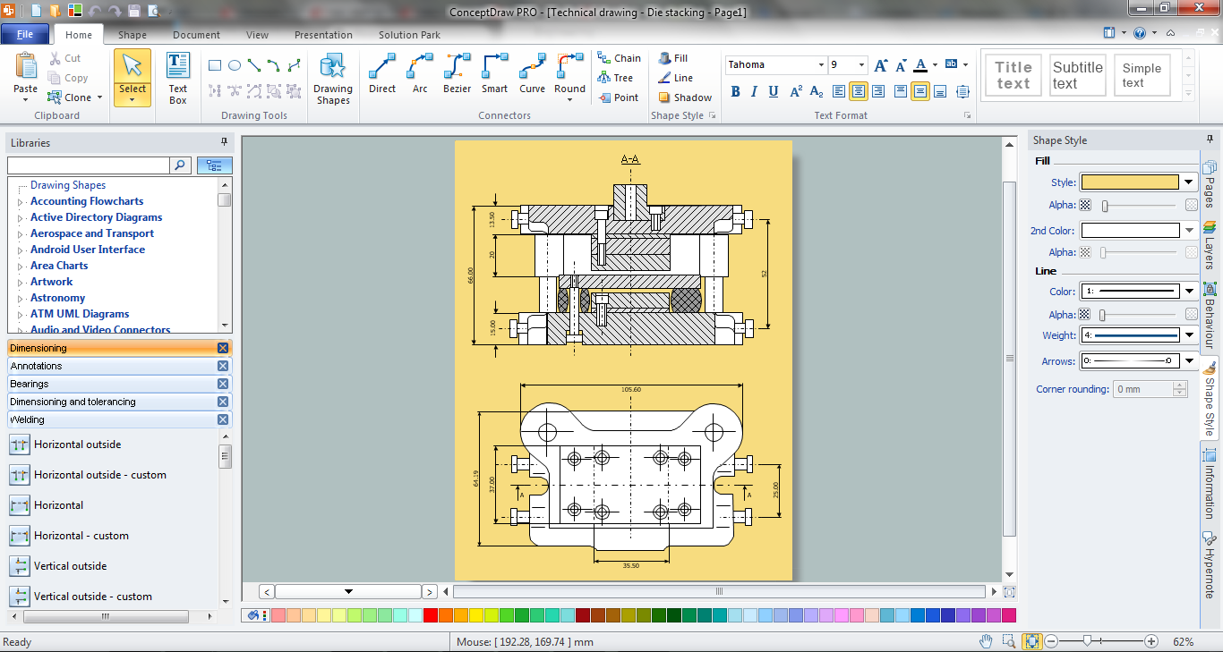
It is impossible to imagine mechanical engineering without drawings which represent various mechanical schemes and designs. ConceptDraw DIAGRAM diagramming and vector drawing software supplied with Mechanical Engineering solution from the Engineering area of ConceptDraw Solution Park offers the set of useful tools which make it a powerful Mechanical Drawing Software.Electrical Symbols — Thermo
A thermocouple is an electrical device consisting of two different conductors forming electrical junctions at differing temperatures. A thermocouple produces a temperature-dependent voltage as a result of the thermoelectric effect, and this voltage can be interpreted to measure temperature. Thermocouples are a widely used type of temperature sensor. 26 libraries of the Electrical Engineering Solution of ConceptDraw DIAGRAM make your electrical diagramming simple, efficient, and effective. You can simply and quickly drop the ready-to-use objects from libraries into your document to create the electrical diagram.Electrical Symbols — Inductors
An inductor, also called a coil or reactor, is a passive two-terminal electrical component which resists changes in electric current passing through it. It consists of a conductor such as a wire, usually wound into a coil. Energy is stored in a magnetic field in the coil as long as current flows. When the current flowing through an inductor changes, the time-varying magnetic field induces a voltage in the conductor, according to Faraday’s law of electromagnetic induction. 26 libraries of the Electrical Engineering Solution of ConceptDraw DIAGRAM make your electrical diagramming simple, efficient, and effective. You can simply and quickly drop the ready-to-use objects from libraries into your document to create the electrical diagram.
 Telecom and AV Circuits
Telecom and AV Circuits solution includes professionally designed samples and collection of pre-made vector elements of antennas, waveguides, antenna TV, audio, video, TV and telegraph equipment, etc. They assist in issues of automation, electrical engineering, designing schematics for amplifiers, receivers, TV audio video transmitters, telephone and radio circuits, making visualizations for telecommunication networks, wireless radio networks, layouts for the video systems. The solution tools help to present the innovations in telecommunications and AV, describe the construction of modern video and audio codecs, architectures and algorithms, specialized network protocols. Design efficiently the 3 way switch diagram, show the structure of a telecommunications network, its logic and configuration, transmit, receive and amplify audio and video signals.
 Digital Electronics
The Digital Electronics solution for ConceptDraw DIAGRAM includes a collection of multifarious diagrams samples and a large number of pre-made vector objects and digital electrical symbols of integrated circuit and connections, logic gate symbols of different kinds, electronic logic and flip flop symbols, etc. These symbols are perfect for logic diagram design, constructing schematics for digital electronics circuits and equipment, decoder, analog to digital converter, and more schematics. Use the solution tools at all stages of electrical engineering and digital electronics design.
How To use House Electrical Plan Software
How we can conduct the electricity at house correctly without a plan? It is impossible. The House electrical diagram depicts locations of switches, outlets, dimmers and lights, and lets understand how you will connect them. But design of House Electrical Plan looks a complex task at a glance, which requires a lot of tools and special experience. But now all is simple with all-inclusive floor plan software - ConceptDraw DIAGRAM. As a house electrical plan software, the ConceptDraw DIAGRAM contains libraries with a large range of professional lighting and electrical symbols, ready-to-use electrical plans samples and examples, and built-in templates for creating great-looking Home floor electrical plans. It is a fastest way to draw Electrical circuit diagrams, Electrical wiring and Circuit schematics, Digital circuits, Electrical equipment, House electrical plans, Satellite television, Cable television, Home cinema, Closed-circuit television when are used the tools of Electric and Telecom Plans Solution from ConceptDraw Solution Park. Files created in Visio for Mac app can be easily imported to ConceptDraw DIAGRAM. Also you may import stencils and even libraries. Try for free an alternative to Visio that Apple users recommend.
- Simple Flow Chart | Electrical Drawing Software and Electrical ...
- SWOT Analysis | Venn Diagram Examples for Problem Solving ...
- Process Flowchart | Design elements - Logic gate diagram | Network ...
- Business Process Flowchart Symbols | Types of Flowcharts | Cloud ...
- Mechanical Drawing Symbols | Technical Drawing Software ...
- Mechanical Drawing Symbols | Process Flow Diagram Symbols ...
- Transistors | Design elements - Semiconductor diodes | MS Visio ...
- Mechanical Drawing Symbols | Basic Flowchart Symbols and Meaning
- Process Flow Diagram Symbols | Technical Drawing Software ...


