Mechanical Drawing Symbols
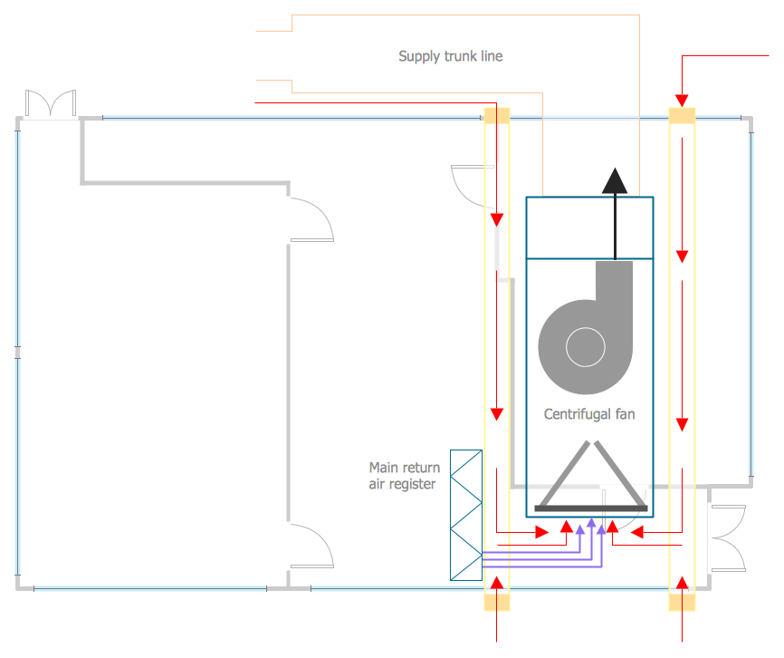
Mechanical Drawings are the special type of technical diagrams that visualize the structure of complex systems and illustrate the information about ventilation, heating, air conditioning, i.e. HVAC systems. These drawings are created on the base of floor plans and reflected ceiling plans, and then become an obligatory part of construction project which is needed directly for construction a building and for receiving a permit on it. Mechanical drawings and diagrams help effectively represent construction, technical and engineering solutions, and also schematics of different mechanical equipment. ConceptDraw DIAGRAM ector drawing software enhanced with Mechanical Engineering solution from Engineering area of ConceptDraw Solution Park provides wide set of effective drawing tools, predesigned mechanical drawing symbols, templates, samples and examples. Use of standardized and recognized mechanical vector symbols helps you design understandable mechanical drawings, diagrams and mechanical engineering schematics.The vector stencil library "HVAC controls" contains contains 24 HVAC control symbols: sensors, actuators, timers, controllers, I/ O points.
Use it for drawing HVAC system diagrams, heating, ventilation, air conditioning, refrigeration, automated building control, and environmental control design floor
plans and equipment layouts.
"HVAC (... Heating, Ventilation and Air Conditioning) is a control system that applies regulation to a heating and/ or air conditioning system. ...
Central controllers and most terminal unit controllers are programmable, meaning the direct digital control program code may be customized for the intended use. The program features include time schedules, setpoints, controllers, logic, timers, trend logs, and alarms. The unit controllers typically have analog and digital inputs that allow measurement of the variable (temperature, humidity, or pressure) and analog and digital outputs for control of the transport medium (hot/ cold water and/ or steam). Digital inputs are typically (dry) contacts from a control device, and analog inputs are typically a voltage or current measurement from a variable (temperature, humidity, velocity, or pressure) sensing device. Digital outputs are typically relay contacts used to start and stop equipment, and analog outputs are typically voltage or current signals to control the movement of the medium (air/ water/ steam) control devices such as valves, dampers, and motors." [HVAC control system. Wikipedia]
The vector stencils example "Design elements - HVAC controls" is included in HVAC Plans solution from the Building Plans area of ConceptDraw Solution
Park.
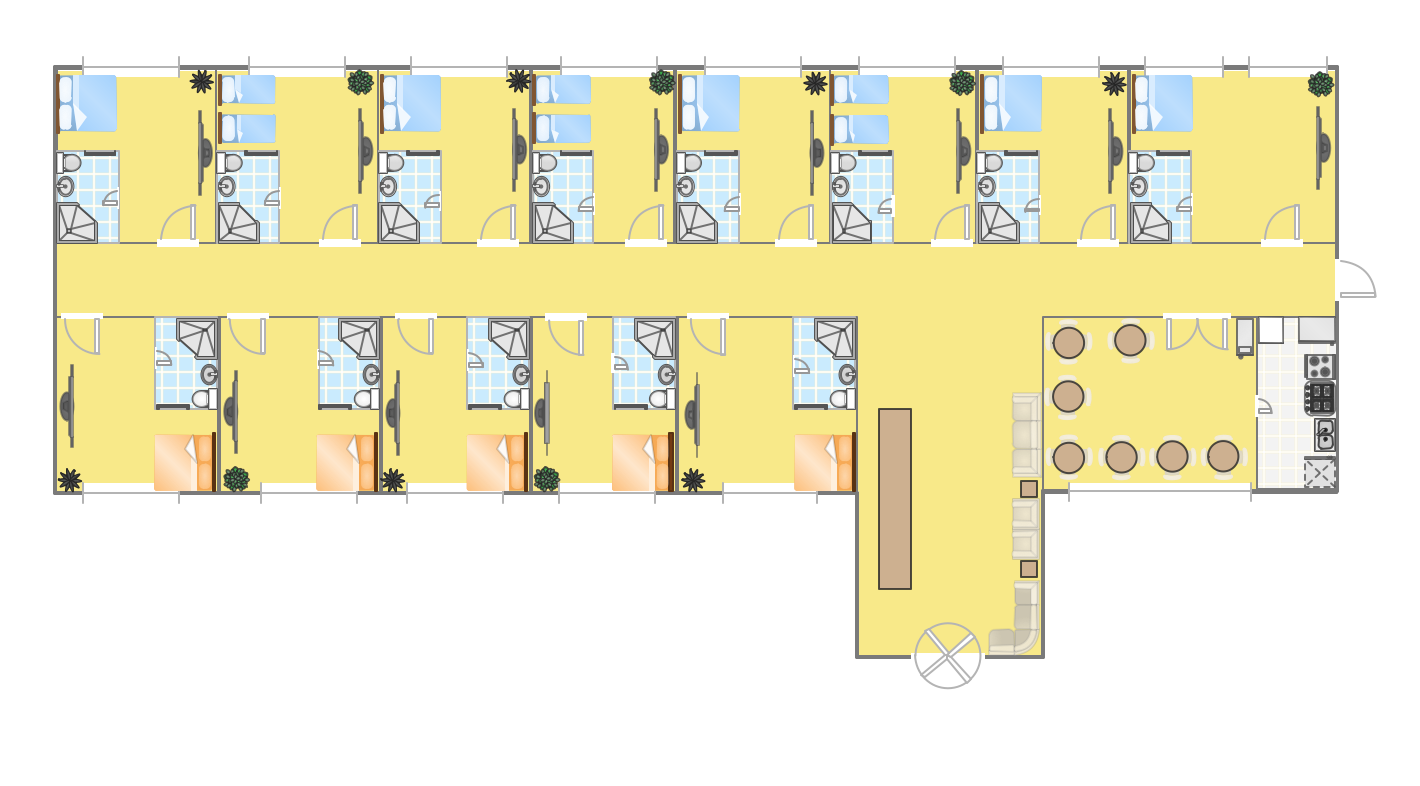
Hotel Plan. Hotel Plan Examples
The hotels vary hard enough by the rating, service level, cost, size, location, style, and many other parameters. Before beginning the construction of new hotel, inn or a hotel complex, you first need to create a detailed overall hotel plan, the location plans of rooms, lobby, restaurant and other common premises and service rooms. The projects of mini-hotels must use the space particularly rational, at the same time the large hotels can afford spacious halls, banquet halls and even terraces. ConceptDraw DIAGRAM diagramming and vector drawing software enhanced with Basic Floor Plans and Floor Plans solutions from the Building Plans area of ConceptDraw Solution Park offer the set of predesigned vector stencils libraries with large selection of symbols of interior design elements, furniture and equipment for easy drawing the Hotel plans, Hotel floor plans, Hotel design plans, Space layouts, Layouts of furniture and equipment, etc. The offered templates and Floor plan samples will be also useful for you.HelpDesk
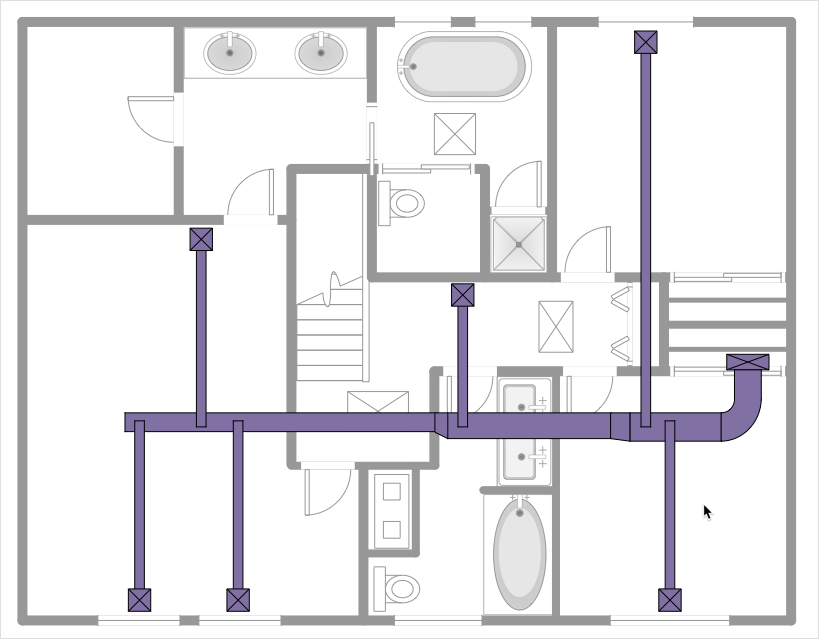
How to Create a HVAC Plan
HVAC plans are used to make and maintain systems of heating and air conditioning. HVAC plan is an important part of building planning. It is developed for private family houses as well as for apartment and public buildings. Making HVAC plans as a part of construction documentation package essential requirement for any building project. Making a plan that shows the location and connection of HVAC equipment involves many different elements that can be managed using ConceptDraw DIAGRAM reinforced with HVAC Plans solution. With ConceptDraw DIAGRAM you can easily create and communicate HVAC plans of any complexity.HVAC Business Plan
Long time you have looked for the convenient and helpful software for drawing HVAC Business Plan? Now ConceptDraw DIAGRAM diagramming and vector drawing software offers you the HVAC Plans Solution from the Building Plans Area that will help you create any desired HVAC Business Plan.- Ac Unit Symbol
- Symbol For Ac Point In Plan
- Air Conditioner Symbol Floor Plan
- Engineering Drawing Symbols Ppt
- Mechanical Engineering Symbols Powerpoint
- Process Flow Diagram Symbols | Air Vent Instrument Symbol
- Vector Powerpoint Gauge
- Design elements - HVAC controls | HVAC controls - Vector stencils ...
- Piping Drawing Basic Symbol Power Point Pdf
- Technical Drawing Software | How To Make a PowerPoint ...
- Mechanical Drawing Symbols | Design elements - Dimensioning ...
- Mechanical Design Engineer Hvac Drawings Symbols
- Electrical Symbol For Double Socket Outlet
- Symbol For A Powerpoint On Electrical Plan
- Electrical Workshop Symbols
- Process Flow Diagram Symbols | How To use House Electrical Plan ...
- Mechanical Engineering Drawing Symbol Of Power Plug
- How To use House Electrical Plan Software | Electrical Symbols ...
- Mechanical Engineering Drawing Symbols Ppt
- Mechanical Engineering Drawing Ppt


