HelpDesk
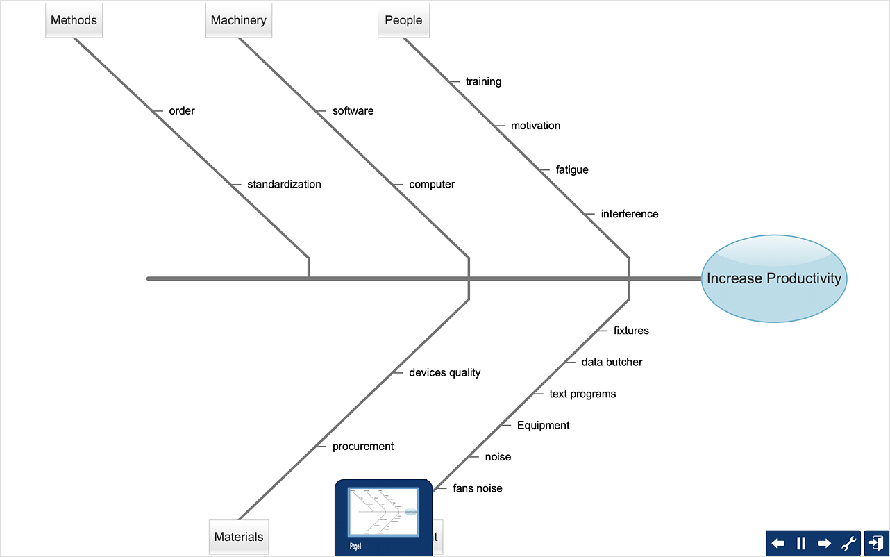
How to Create a Fishbone (Ishikawa) Diagram Quickly
A Fishbone (Ishikawa) diagram is also called cause-and-effect diagram. Fishbone diagram is often used in business to determine the cause of some problem. The diagram illustrates the main causes and sub-causes leading to an event. The main goal of the Fishbone diagram is to illustrate in a graphical way the relationship between a given outcome and all the factors that influence this outcome. The complete diagram resembles a fish skeleton as its name implies. The ability to create a Fishbone Diagram is supported by the Fishbone Diagram solution. Use ConceptDraw MINDMAP for structuring data and then ConceptDraw DIAGRAM for generating a Fishbone Diagram from mind map structure.HelpDesk
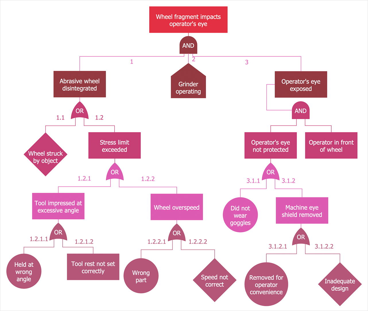
How to Create a Fault Tree Analysis Diagram (FTD)
Fault Tree Diagram is a logic diagram that shows the state of an entire system in a relationship of the conditions of its elements. Fault Tree Diagram is used to analyze the probability of functional system failures and safety accidents. ConceptDraw DIAGRAM allows you to create professional Fault Tree Diagrams using the basic FTD symbols. An FTD visualizes a model of the processes within a system that can lead to the unlikely event. A fault tree diagrams are created using standard logic symbols. The basic elements in a fault tree diagram are gates and events.- Basic Flowchart Symbols and Meaning | Data Flow Diagram ...
- Algorithm Design And Analysis Process In Flow Chart
- Basic Flowchart Symbols and Meaning | Euclidean algorithm ...
- With The Help Of Flow Chart Explain Various Steps Of Algorithms
- Diagram of a Pyramid | Pyramid Diagram | Competitor Analysis ...
- Explain An Algorithm Using A Diagram
- Flow Chart Stages Of Algorithm Design And Analysis Process
- Design And Analysis Of Algorithm Flowchart
- Basic Flowchart Symbols and Meaning | Process Flowchart | Data ...
- Basic Flowchart Symbols and Meaning | Data Flow Diagram ...
- Algorithm Steps Diagram
- Euclidean algorithm - Flowchart | Seven Basic Tools of Quality ...
- Basic Flowchart Symbols and Meaning | Process Flowchart ...
- Algorithm Design And Analysis Process Diagram
- Euclidean algorithm - Flowchart | Solving quadratic equation ...
- Basic Flowchart Symbols and Meaning | Software Diagrams | Types ...
- Solving quadratic equation algorithm - Flowchart | Basic ...
- Process Flowchart | Basic Flowchart Symbols and Meaning | Flow ...
- Basic Flowchart Symbols and Meaning | Audit Flowchart Symbols ...
- Euclidean algorithm - Flowchart | PROBLEM ANALYSIS . Identify and ...

