HelpDesk
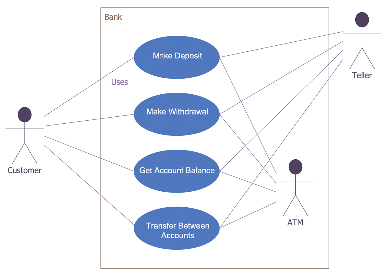
How to Create a Bank ATM Use Case Diagram
UML diagrams are often used in banking management for documenting a banking system. In particular, the interaction of bank customers with an automated teller machine (ATM) can be represented in a Use Case diagram. Before the software code for an ATM, or any other system design, is written, it is necessary to create a visual representation of any object-oriented processes. This is done most effectively by creating a Unified Modeling Language (UML) diagram, using object-oriented modeling. UML works as a general purpose modeling language for software engineers or system analysts, offering a number of different diagram styles with which to visually depict all aspects of a software system. ConceptDraw DIAGRAM diagramming software, enhanced and expanded with the ATM UML Diagrams solution, offers the full range of icons, templates and design elements needed to faithfully represent ATM and banking information system architecture using UML standards. The ATM UML Diagrams solution is useful for beginner and advanced users alike. More experienced users will appreciate a full range of vector stencil libraries and ConceptDraw DIAGRAM 's powerful software, that allows you to create your ATM UML diagram in a matter of moments.Data structure diagram with ConceptDraw DIAGRAM
Data structure diagram (DSD) is intended for description of conceptual models of data (concepts and connections between them) in the graphic format for more obviousness. Data structure diagram includes entities description, connections between them and obligatory conditions and requirements which connect them. Create Data structure diagram with ConceptDraw DIAGRAM.Bubble diagrams in Landscape Design with ConceptDraw DIAGRAM
Bubble Diagrams are the charts with a bubble presentation of data with obligatory consideration of bubble's sizes. They are analogs of Mind Maps and find their application at many fields, and even in landscape design. At this case the bubbles are applied to illustrate the arrangement of different areas of future landscape design, such as lawns, flowerbeds, playgrounds, pools, recreation areas, etc. Bubble Diagram helps to see instantly the whole project, it is easy for design and quite informative, in most cases it reflects all needed information. Often Bubble Diagram is used as a draft for the future landscape project, on the first stage of its design, and in case of approval of chosen design concept is created advanced detailed landscape plan with specification of plants and used materials. Creation of Bubble Diagrams for landscape in ConceptDraw DIAGRAM software is an easy task thanks to the Bubble Diagrams solution from "Diagrams" area. You can use the ready scanned location plan as the base or create it easy using the special ConceptDraw libraries and templates.- 4 Level pyramid model diagram - Information systems types ...
- Uml Diagrams For Atm Ppt
- Difference Between Activity And Swimlane Diagram
- UML activity diagram - Cash withdrawal from ATM | UML Activity ...
- Design elements - UML interaction overview diagrams ...
- UML Diagram | Design elements - UML interaction overview ...
- Basic Flowchart Symbols and Meaning | Process Flowchart | Types ...
- Interaction Diagram For Banking System
- Difference Between Activity Diagram And Components Vector
- Diagramming Software for Design UML Interaction Overview Diagrams
- Cross-Functional Flowchart (Swim Lanes) | Swim Lane Diagrams ...
- Bank Activity Diagram
- Design elements - Bank UML sequence diagram
- Diagramming Software for Design UML Collaboration Diagrams ...
- Diagramming Software for Design UML Interaction Overview Diagrams
- Difference Between Component And Deployment Diagram
- Banking System | Bank System | UML Diagram | Overview Diagram ...
- UML state machine diagram - Template | Design elements - Bank ...
- Is A Class Model A Class Diagram Difference Between
- UML Diagram | Design Elements for UML Diagrams | UML Business ...


