Electrical Symbols, Electrical Diagram Symbols

Electrical Symbols — Analog and Digital Logic

Electrical Symbols — Logic Gate Diagram

Electrical Symbols — Composite Assemblies

Electrical Symbols, Electrical Schematic Symbols

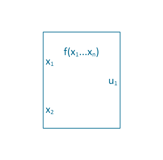
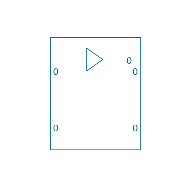
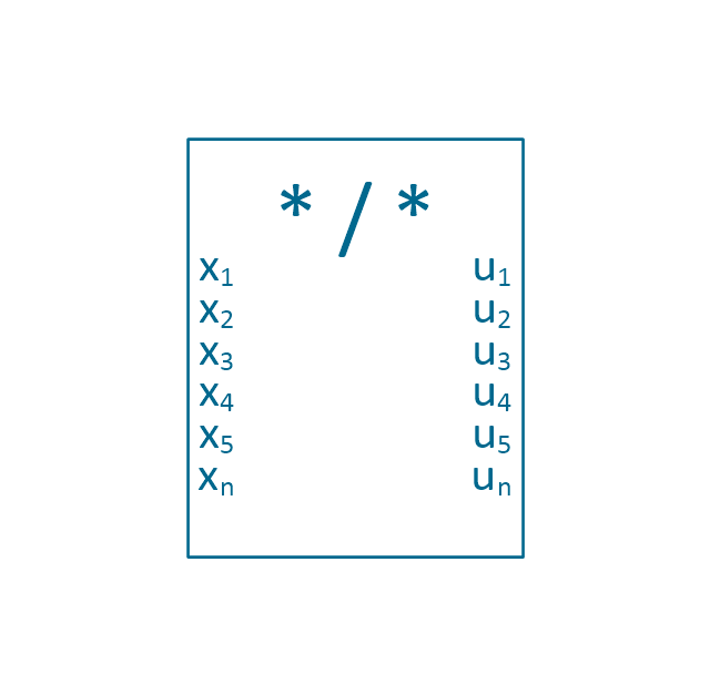
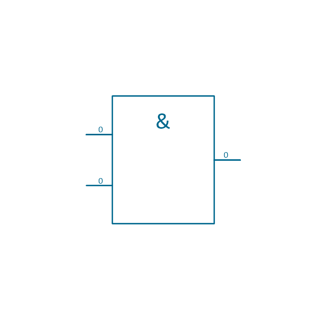
The vector stencils library "Analog and digital logic" contains 40 element symbols of logic (threshold) gates, bistable current switches, current controllers, regulators, electrical generators, and amplifiers.
Use it for drawing the digital and analog functions in electronic circuit diagrams and electrical schematics in the ConceptDraw PRO diagramming and vector drawing software extended with the Electrical Engineering solution from the Engineering area of ConceptDraw Solution Park.
www.conceptdraw.com/ solution-park/ engineering-electrical
Clock

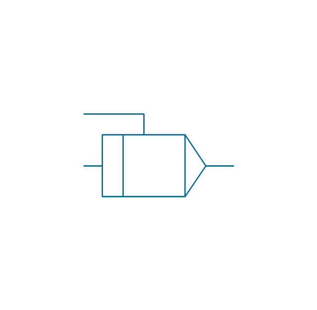
Function generator
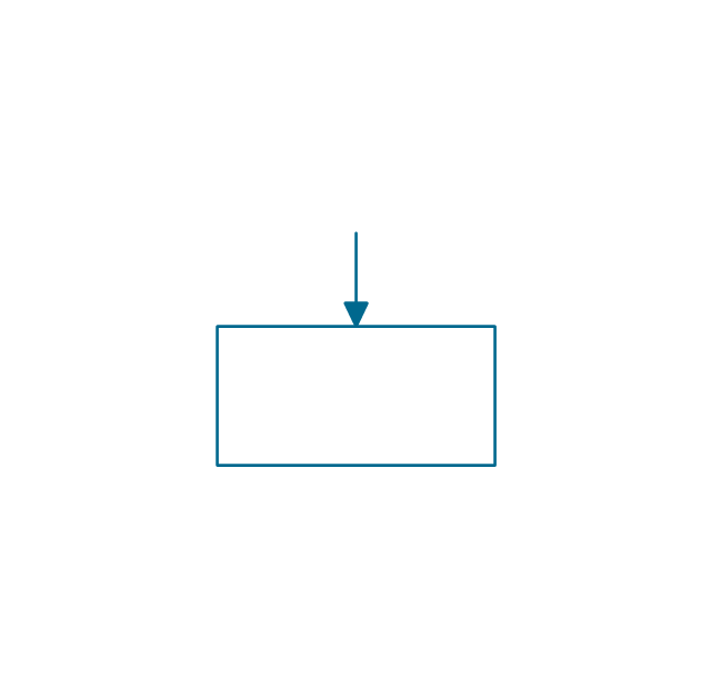
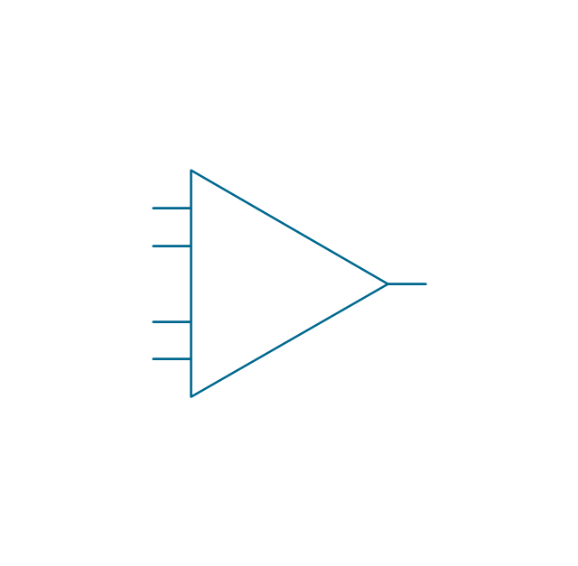
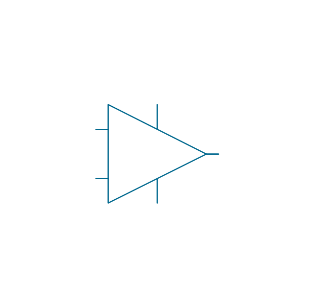
Amplifier
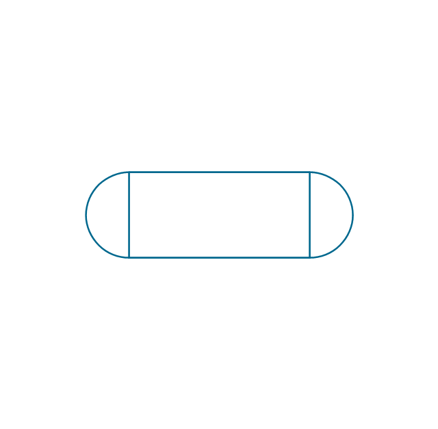
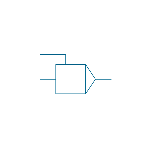
Converter
Logic gates
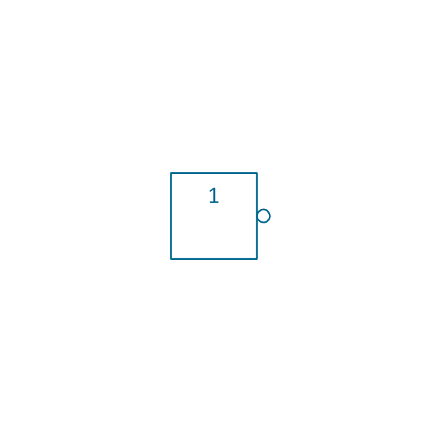
Inverter

Inverter 2
Buffer

Buffer 2

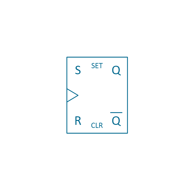
RS Flip-flop
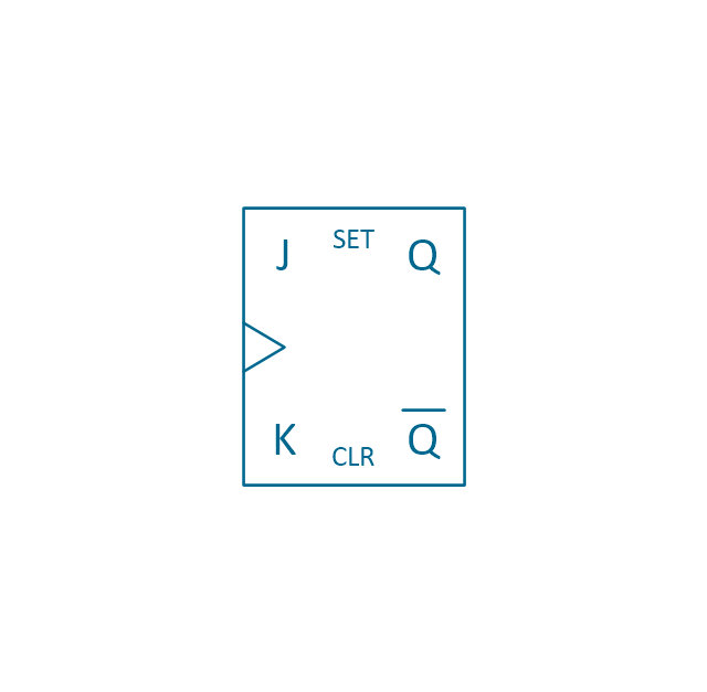
JK Flip-flop
Latch Flip-flop
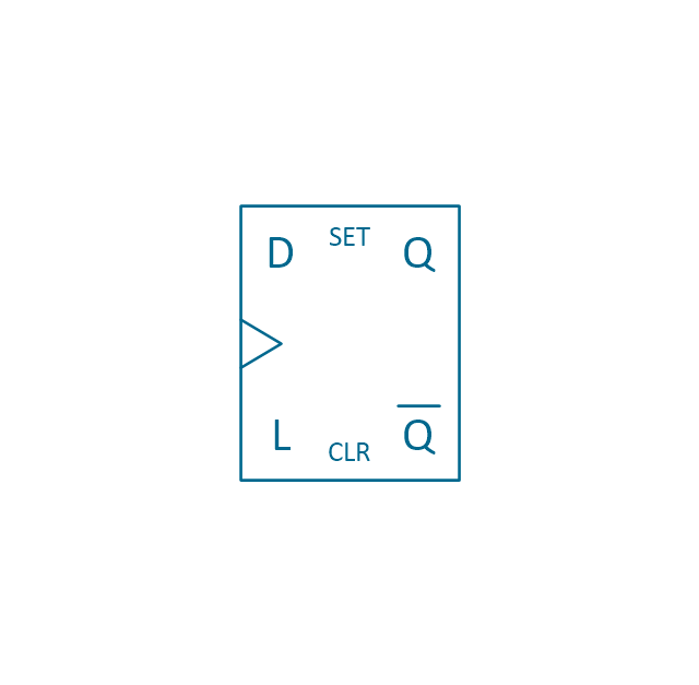
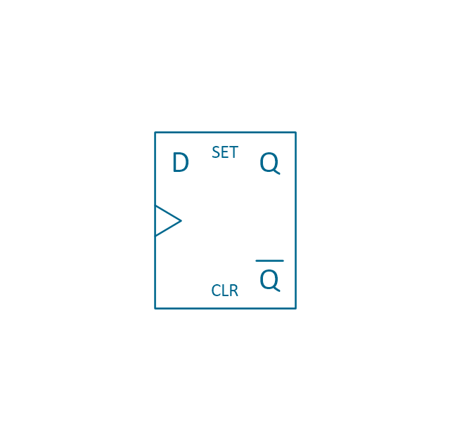
D Flip-flop
Analog symbol

Digital symbol

Negative logic dot

Potentiometer

Potentiometer 2
Positional servo
Piezoelectric crystal, 4 electrodes

Piezoelectric crystal, 3 electrodes

Piezoelectric crystal, 2 electrodes

I/O port bidirectional

I/O port unidirectional

Square signal

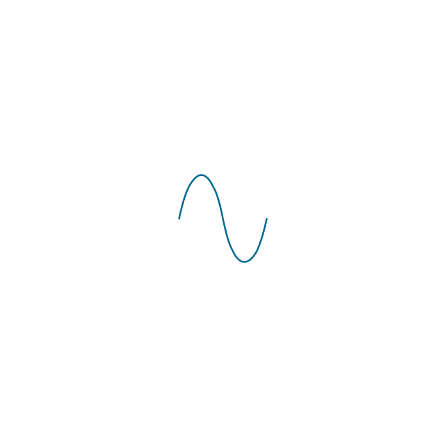
Sine wave signal
Sawtooth signal

Ramp signal

3 state data signal

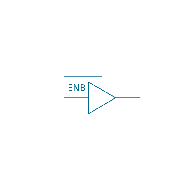
Three-state buffer
Integrator
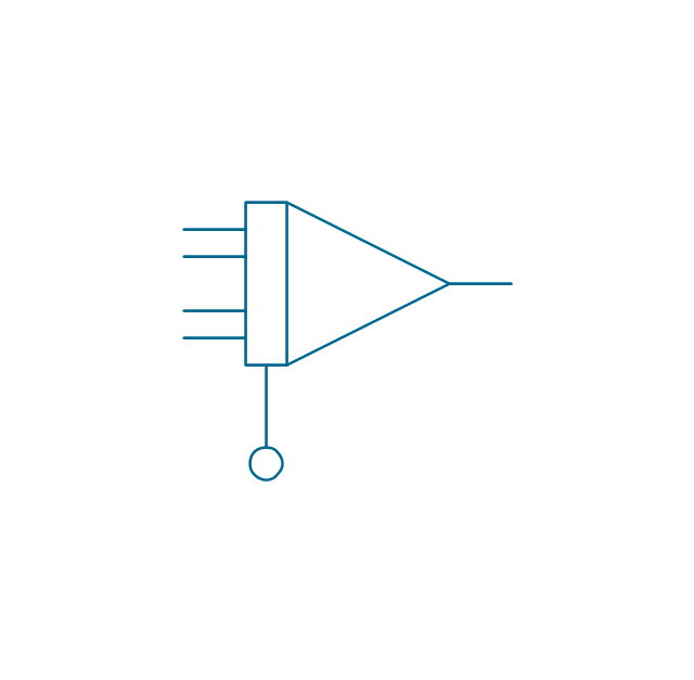
Summing amplifier
Multiplier

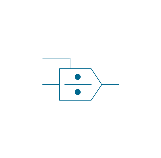
Divider
Function generator 2
Generalized integrator
Operational amplifier

Operational amplifier 2
Switch point

Switch point 2

Electrical Symbols — Maintenance

The vector stencils library "Analog and digital logic" contains 40 element symbols of logic (threshold) gates, bistable current switches, current controllers, regulators, electrical generators, and amplifiers.
Use it for drawing the digital and analog functions in electronic circuit diagrams and electrical schematics in the ConceptDraw PRO diagramming and vector drawing software extended with the Electrical Engineering solution from the Engineering area of ConceptDraw Solution Park.
www.conceptdraw.com/ solution-park/ engineering-electrical
Use it for drawing the digital and analog functions in electronic circuit diagrams and electrical schematics in the ConceptDraw PRO diagramming and vector drawing software extended with the Electrical Engineering solution from the Engineering area of ConceptDraw Solution Park.
www.conceptdraw.com/ solution-park/ engineering-electrical
Clock
Function generator
Amplifier
Converter
Logic gates
Inverter
Inverter 2
Buffer
Buffer 2
RS Flip-flop
JK Flip-flop
Latch Flip-flop
D Flip-flop
Analog symbol
Digital symbol
Negative logic dot
Potentiometer
Potentiometer 2
Positional servo
Piezoelectric crystal, 4 electrodes
Piezoelectric crystal, 3 electrodes
Piezoelectric crystal, 2 electrodes
I/O port bidirectional
I/O port unidirectional
Square signal
Sine wave signal
Sawtooth signal
Ramp signal
3 state data signal
Three-state buffer
Integrator
Summing amplifier
Multiplier
Divider
Function generator 2
Generalized integrator
Operational amplifier
Operational amplifier 2
Switch point
Switch point 2
Electrical Symbols — VHF UHF SHF

The vector stencils library "Analog and digital logic" contains 40 element symbols of logic (threshold) gates, bistable current switches, current controllers, regulators, electrical generators, and amplifiers.
Use it for drawing the digital and analog functions in electronic circuit diagrams and electrical schematics in the ConceptDraw PRO diagramming and vector drawing software extended with the Electrical Engineering solution from the Engineering area of ConceptDraw Solution Park.
www.conceptdraw.com/ solution-park/ engineering-electrical
Use it for drawing the digital and analog functions in electronic circuit diagrams and electrical schematics in the ConceptDraw PRO diagramming and vector drawing software extended with the Electrical Engineering solution from the Engineering area of ConceptDraw Solution Park.
www.conceptdraw.com/ solution-park/ engineering-electrical
Clock
Function generator
Amplifier
Converter
Logic gates
Inverter
Inverter 2
Buffer
Buffer 2
RS Flip-flop
JK Flip-flop
Latch Flip-flop
D Flip-flop
Analog symbol
Digital symbol
Negative logic dot
Potentiometer
Potentiometer 2
Positional servo
Piezoelectric crystal, 4 electrodes
Piezoelectric crystal, 3 electrodes
Piezoelectric crystal, 2 electrodes
I/O port bidirectional
I/O port unidirectional
Square signal
Sine wave signal
Sawtooth signal
Ramp signal
3 state data signal
Three-state buffer
Integrator
Summing amplifier
Multiplier
Divider
Function generator 2
Generalized integrator
Operational amplifier
Operational amplifier 2
Switch point
Switch point 2
- Amplifier - Circuit diagram | Electrical Symbols , Electrical Diagram ...
- Power Amplifier Symbol
- Design elements - Logic gate diagram | Symbol Amplifier Diagram
- Electrical Symbols , Electrical Diagram Symbols | Amplifier - Circuit ...
- Volume Control Symbol In Audio Amplifier Circuit Diagram
- Circuit diagram - EL 34 schematics | Electrical Symbols — Electron ...
- Symbol Meaning Of Diagram Lay Out Of Amplifier
- Circuit diagram - EL 34 schematics | Valve Amplifier Circuit Diagrams
- Electrical Symbols , Electrical Diagram Symbols | Electrical Symbols ...
- Symbol Amplifier Audio