Electrical Symbols — Analog and Digital Logic

The vector stencils library "Analog and digital logic" contains 40 element symbols of logic (threshold) gates, bistable current switches, current controllers, regulators, electrical generators, and amplifiers.
Use it for drawing the digital and analog functions in electronic circuit diagrams and electrical schematics in the ConceptDraw PRO diagramming and vector drawing software extended with the Electrical Engineering solution from the Engineering area of ConceptDraw Solution Park.
www.conceptdraw.com/ solution-park/ engineering-electrical
Clock

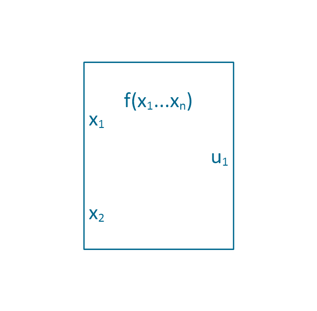
Function generator
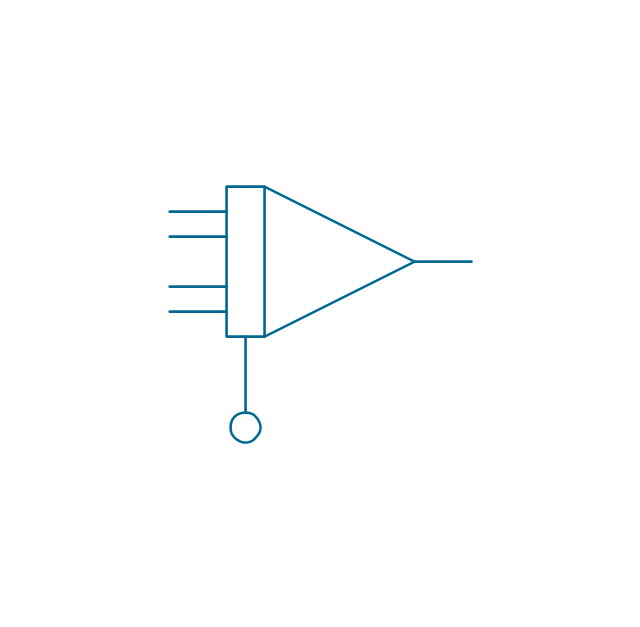
Amplifier
Converter
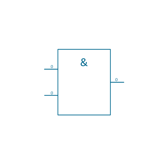
Logic gates
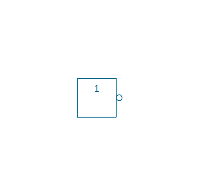
Inverter

Inverter 2
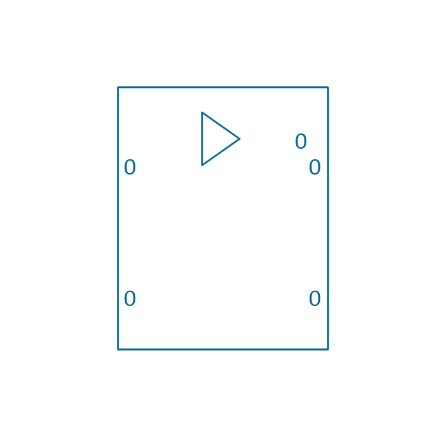
Buffer

Buffer 2

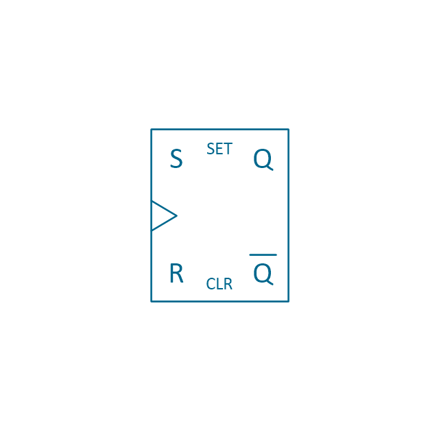
RS Flip-flop
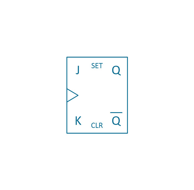
JK Flip-flop
Latch Flip-flop
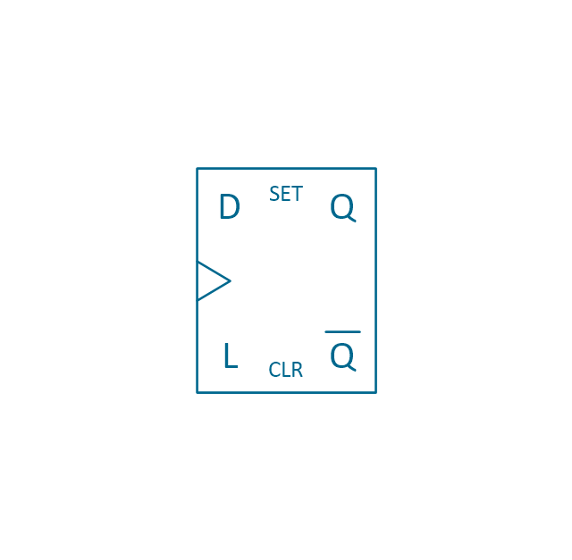
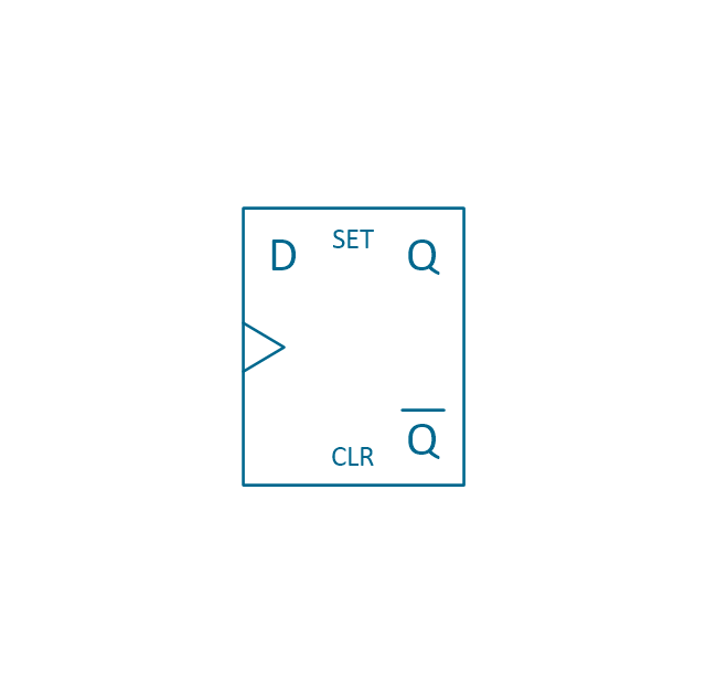
D Flip-flop
Analog symbol

Digital symbol

Negative logic dot

Potentiometer

Potentiometer 2
Positional servo
Piezoelectric crystal, 4 electrodes

Piezoelectric crystal, 3 electrodes

Piezoelectric crystal, 2 electrodes

I/O port bidirectional

I/O port unidirectional

Square signal

Sine wave signal

Sawtooth signal

Ramp signal

3 state data signal

Three-state buffer

Integrator
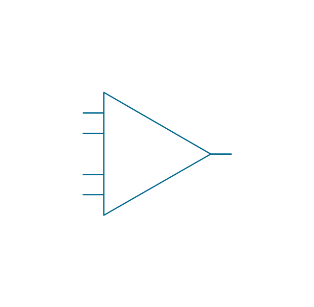
Summing amplifier
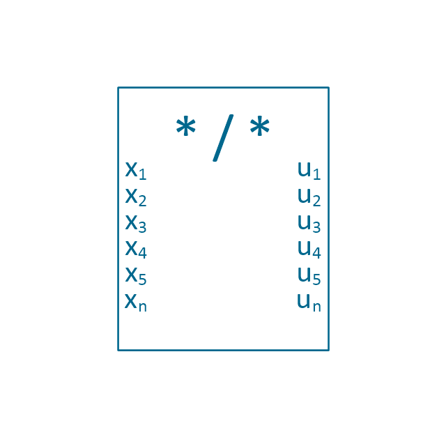
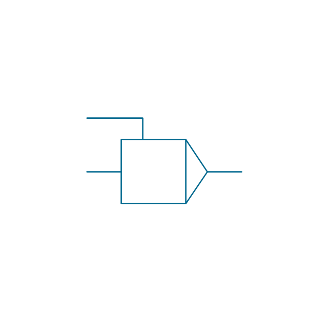
Multiplier

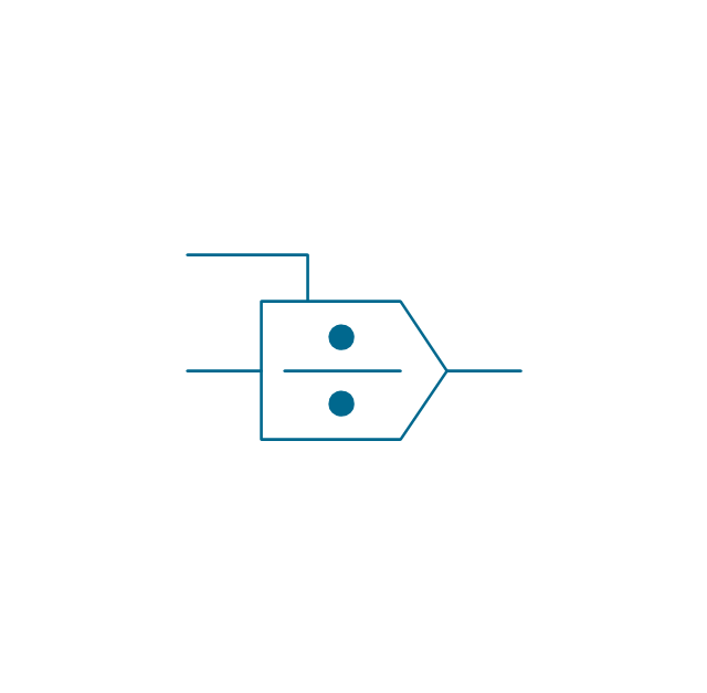
Divider
Function generator 2
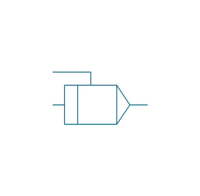
Generalized integrator
Operational amplifier

Operational amplifier 2
Switch point

Switch point 2

Electrical Symbols, Electrical Diagram Symbols

Electrical Drawing Software and Electrical Symbols

Electrical Symbols, Electrical Schematic Symbols

The vector stencils library "Analog and digital logic" contains 40 element symbols of logic (threshold) gates, bistable current switches, current controllers, regulators, electrical generators, and amplifiers.
Use it for drawing the digital and analog functions in electronic circuit diagrams and electrical schematics.
"Analogue electronics (or analog in American English) are electronic systems with a continuously variable signal, in contrast to digital electronics where signals usually take only two different levels. The term "analogue" describes the proportional relationship between a signal and a voltage or current that represents the signal." [Analogue electronics. Wikipedia]
"Digital electronics, or digital (electronic) circuits, represent signals by discrete bands of analog levels, rather than by a continuous range. All levels within a band represent the same signal state. Relatively small changes to the analog signal levels due to manufacturing tolerance, signal attenuation or parasitic noise do not leave the discrete envelope, and as a result are ignored by signal state sensing circuitry.
In most cases the number of these states is two, and they are represented by two voltage bands: one near a reference value (typically termed as "ground" or zero volts) and a value near the supply voltage, corresponding to the "false" ("0") and "true" ("1") values of the Boolean domain respectively.
Digital techniques are useful because it is easier to get an electronic device to switch into one of a number of known states than to accurately reproduce a continuous range of values.
Digital electronic circuits are usually made from large assemblies of logic gates, simple electronic representations of Boolean logic functions." [Digital electronics. Wikipedia]
The example "Design elements - Analog and digital logic" was drawn using the ConceptDraw PRO diagramming and vector drawing software extended with the Electrical Engineering solution from the Engineering area of ConceptDraw Solution Park.
Analog and digital logic elements

Electrical Diagram

Wiring Diagrams with ConceptDraw DIAGRAM

Electrical Symbols — Logic Gate Diagram

Electrical Symbols — Integrated Circuit

Electrical Symbols — Delay Elements

Electrical Symbols — Composite Assemblies

Electrical Symbols — Rotating Equipment

Electrical Symbols — Qualifying

Cisco Optical. Cisco icons, shapes, stencils and symbols

- Design elements - Analog and digital logic | Electrical Symbols ...
- Design elements - Analog and digital logic | American Symbols For ...
- Electrical Drawing Software and Electrical Symbols | Design ...
- Electrical Symbols , Electrical Diagram Symbols | Electrical Symbols ...
- Electrical Symbols — Resistors | Electrical Symbols — Analog and ...
- Analog and digital logic - Vector stencils library | Design elements ...
- Electrical Symbols — Analog and Digital Logic | Electrical Symbols ...
- Electrical Symbols — Maintenance | Electrical Symbols — Analog ...
- Electrical Symbols — Delay Elements | Analog and digital logic ...
- 2-bit ALU - Logic gate diagram | | Analog and digital logic - Vector ...
- Interior Design Site Plan - Design Elements | | Analog and digital ...
- Electrical Symbols — Maintenance | Electrical Symbols ...
- Electrical Drawing Software and Electrical Symbols | Electrical ...
- Analog and digital logic - Vector stencils library | How To use House ...
- Cross-Functional Flowchart | Design elements - Analog and digital ...
- Flowchart design. Flowchart symbols , shapes, stencils and icons ...
- Design elements - Analog and digital logic | Analog and digital logic ...
- State Diagram Example In Digital Logic Design
- Electrical Drawing Software and Electrical Symbols | Electrical ...
- Digital Electronic Symbols