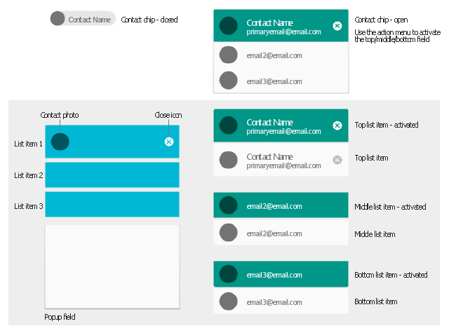
The vector stencils library "Android chips" contains 14 chip elements: contact chips, list items, popup field, contact photo, close icon.
Use it to design user interface of your Android application.
The shapes example "Design elements - Android chips" was created using the ConceptDraw PRO diagramming and vector drawing software extended with the "Android user interface" solution from the "Software Development" area of ConceptDraw Solution Park.
 Android User Interface
The Android User Interface solution allows ConceptDraw DIAGRAM act as an Android UI design tool. Libraries and templates contain a variety of Android GUI elements to help users create images based on Android UI design.
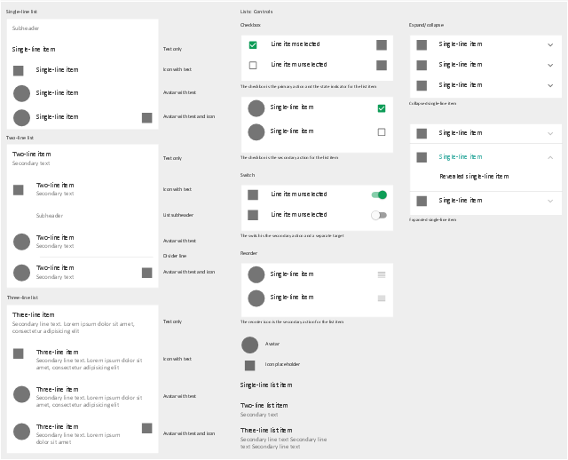
The vector stencils library "Android lists" contains 29 list elements.
Use it to design user interface of your software applications for Android OS with ConceptDraw PRO software.
The shapes example "Design elements - Android lists" was created using the ConceptDraw PRO diagramming and vector drawing software extended with the "Android user interface" solution from the "Software Development" area of ConceptDraw Solution Park.
The vector stencils library "Android lists" contains 20 list elements.
Use it to design user interface of your Android 5 application.
The shapes example "Design elements - Android lists" was created using the ConceptDraw PRO diagramming and vector drawing software extended with the "Android user interface" solution from the "Software Development" area of ConceptDraw Solution Park.
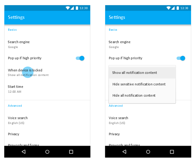
This Android 7 user interface sample shows Material Design simple menu.
"Menus display a list of choices on a transient sheet of material.
Menus appear upon interaction with a button, action, or other control. They display a list of choices, with one choice per line.
Menu items may be disabled if not applicable to a certain context. ...
Use simple menus in lists to display the options for a specific list item. ...
When opened, simple menus attempt to vertically align the currently selected menu item with the list item. The currently selected menu item is highlighted." [material.io/ guidelines/ components/ menus.html]
The Android 7 UI design example "Simple menu" was created using the ConceptDraw PRO diagramming and vector drawing software extended with the "Android user interface" solution from the "Software Development" area of ConceptDraw Solution Park.
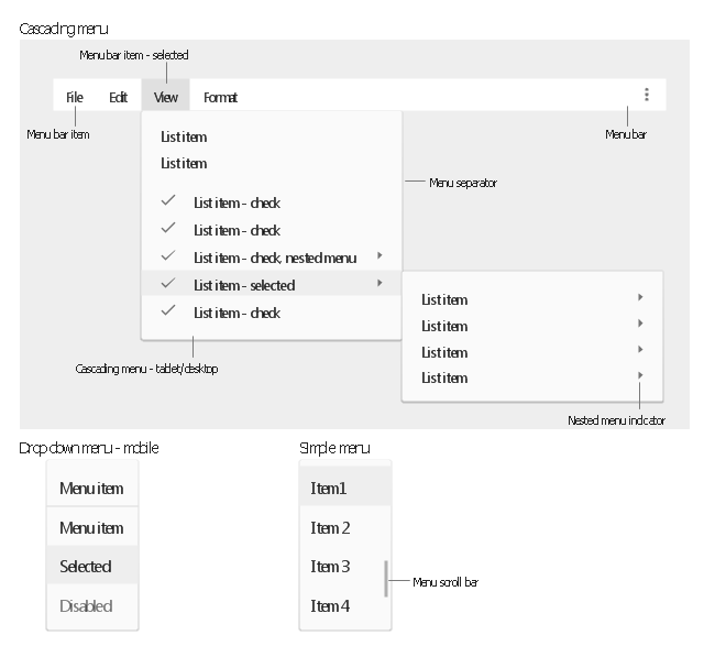
The vector stencils library "Android menus" contains 18 menu elements.
Use it to design user interface of your Android 5 application.
The shapes example "Design elements - Android menus" was created using the ConceptDraw PRO diagramming and vector drawing software extended with the "Android user interface" solution from the "Software Development" area of ConceptDraw Solution Park.
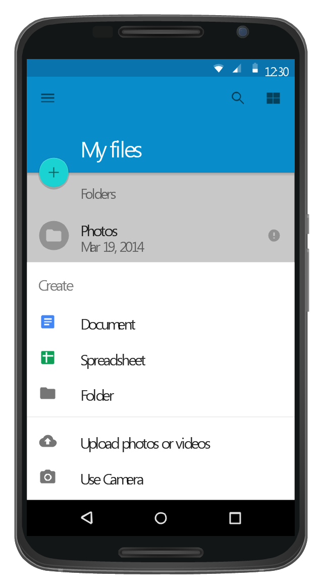
This Android 5 UI design example shows My Files screen of Google Nexus 6 smartphone.
The user interface design example "Android 5.0 - List-style bottom sheet" was created using the ConceptDraw PRO diagramming and vector drawing software extended with the "Android user interface" solution from the "Software Development" area of ConceptDraw Solution Park.
The user interface design example "Android 5.0 - List-style bottom sheet" was created using the ConceptDraw PRO diagramming and vector drawing software extended with the "Android user interface" solution from the "Software Development" area of ConceptDraw Solution Park.
Android GUI
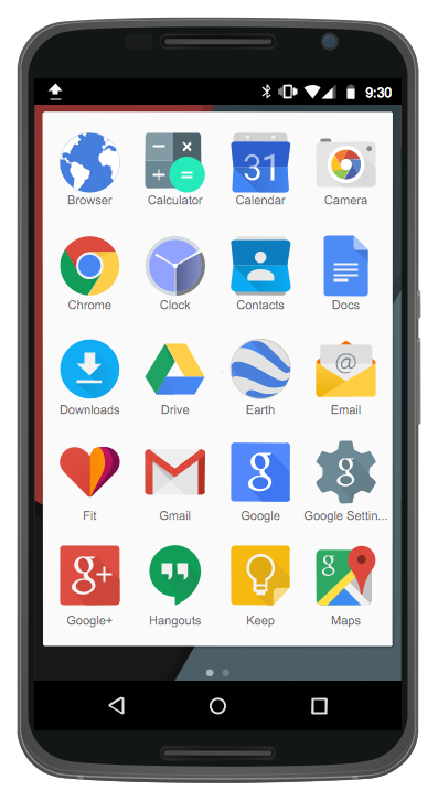
Android is an operating system based on the Linux kernel and developed by Google for smartphones, tablet computers, electronic books, netbooks, smartbooks, digital players, watches, game consoles, TV and other devices. ConceptDraw DIAGRAM extended with Android User Interface Solution from the Software Development Area is a powerful software with extensive drawing tools which can help you to build the intelligible, attractive and easy for perception Android GUI for your application.UML Diagram Types List
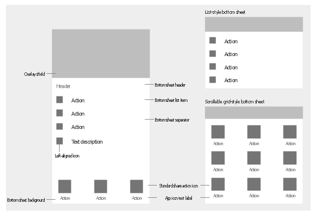
Two types of diagrams are used in UML: Structure Diagrams and Behavior Diagrams. Behavior Diagrams represent the processes proceeding in a modeled environment. Structure Diagrams represent the elements that compose the system.The vector stencils library "Android bottom sheets" contains 11 bottom sheet elements.
Use it to design user interface of your Android application.
The shapes example "Design elements - Android bottom sheets" was created using the ConceptDraw PRO diagramming and vector drawing software extended with the "Android user interface" solution from the "Software Development" area of ConceptDraw Solution Park.
Structured Systems Analysis and Design Method (SSADM) with ConceptDraw DIAGRAM
Structured Systems Analysis and Design Method (abbr. SSADM) is a method developed in Great Britain and accepted in 1993 as a national standard for information systems development and analysis. SSADM is based on Data Flow Diagrams and is characterized with presence of clear sequence of steps at projecting, analysis, and documenting of information system. It involves 6 main stages: analysis of existing system or estimation of practicability, requirements definition, determination of technical requirements and equipment cost, development of logical data model, projecting of logical requirements and specification them, physical projecting. Each of them is also divided into several steps defining the tasks that should be fulfilled at a given stage. The most important SSADM elements are flows modeling with help of DFD, data logic modeling with help of LDS (Logical Data Structure) and description of entities behavior. Applying of SSADM is easy with ConceptDraw DIAGRAM diagramming and vector drawing software and Data Flow Diagram solution.Windows 8 UI Design Patterns
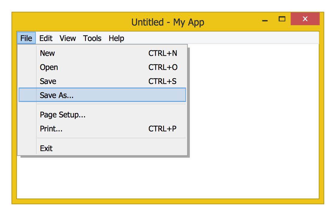
The patterns are commonly used in the field of programming for various electronic devices, mobile devices and PCs. UI design patterns are useful standard solvings for common design problems. There are large quantity of various design and UI patterns. Windows 8 is not exception - in the help to Win8 designers, developers, and software engineers, were developed the Windows 8 UI Design Patterns.ERD Symbols and Meanings
Entity Relationship Diagram (ERD) is a popular software engineering tool for database modeling and illustration the logical structure of databases, which uses one of two notations - Chen's or Crow’s Foot. Crow's foot notation is effective when used in software engineering, information engineering, structured systems analysis and design. Each of these notations applies its own set of ERD symbols. Crow's foot diagrams use boxes to represent entities and lines between these boxes to show relationships. Varied shapes at the ends of lines depict the cardinality of a given relationship. Chen's ERD notation is more detailed way to represent entities and relationships. ConceptDraw DIAGRAM application enhanced with all-inclusive Entity-Relationship Diagram (ERD) solution allows design professional ER diagrams with Chen's or Crow’s Foot notation on your choice. It contains the full set of ready-to-use standardized ERD symbols and meanings helpful for quickly drawing, collection of predesigned ERD samples, examples and templates. ConceptDraw Pro is a great alternative to Visio for Mac users as it offers more features and can easily handle the most demanding professional needs.
GUI Prototyping with ConceptDraw DIAGRAM
All about prototyping. GUI Prototyping with ConceptDraw. Download prototyping software.- List Item Design
- Design elements - Android chips | How to add Several Hyperlinks to ...
- Menu List Design Android
- List Item Android Different Uis
- Design elements - Android chips | Android User Interface | Android ...
- Android Ui Design Software
- Android 5.0 - List -style bottom sheet | Flowchart design . Flowchart ...
- Top 5 Android Flow Chart Apps | Android UI Design Tool ...
- Android 5.0 - List -style bottom sheet | Android 5.0 - Single-line list ...
- Android User Interface | How to Design an Interface Mock-up of an ...
- Design elements - Android system icons (file) | Design elements ...
- Design elements - List blocks | Design elements - Management list ...
- Process Flowchart | Design elements - Android chips | General ...
- Example Design Address List
- Design elements - Android buttons | Android UI Design | Android ...
- Android UI Design
- Controls - Vector stencils library | Design elements - Android UI ...
- Android Software Ui Design
- Design elements - Android chips | Window elements - Vector ...
- Android GUI | Android User Interface | Android User Interface ...
