Entity Relationship Diagram - ERD - Software for Design Crows Foot ER Diagrams
ER-model is a data model which lets describe the conceptual schemes in a specific subject area. It can help to highlight the key entities and specify relationships that can be established between these entities. During the database design, it is realized the transformation of ER model into certain database scheme based on the chosen data model (relational, object, network, etc.). There are used two notations for ERDs: Crow's Foot and Chen's. Crow's Foot notation proposed by Gordon Everest represents the entity by rectangle containing its name (name must be unique within this model), and relation - by the line which links two entities involved in relationship. The relationship's plurality is graphically indicated by a "plug" on the end of the link, the optionality - by a circle. Entity-Relationship Diagrams based on Crow's Foot notation can be easily drawn using the ConceptDraw DIAGRAM. Extended with Entity-Relationship Diagram (ERD) solution, it is the best ERD diagrams software with powerful tools and ready design elements for Crow's Foot and Chen notations.
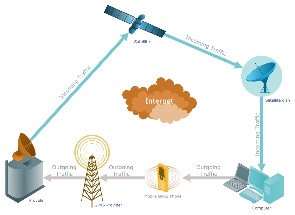
Telecommunications Networks
ConceptDraw DIAGRAM diagramming and vector drawing software provides the Telecommunication Network Diagrams Solution from the Computer and Networks Area for quick and easy drawing the Telecommunications Networks.Network Glossary Definition
The network glossary contains a complete list of network, computer-related and technical terms in alphabetic order, explanations and definitions for them, among them there are words well known for you and also specific, rare-used, uncommon or newly introduced terms. This specialized glossary, also known as a vocabulary, is the best in its field and covers in details the various aspects of computer network technologies. This glossary was developed by specialists using the practical experience and many useful sources to help the ConceptDraw users in their work, you can read and learn it from the screen on-line or print, it can be also used as a perfect educational guide or tutorial. ConceptDraw DIAGRAM software extended with Computer and Networks solution is easy to draw various types of Network diagrams, Network topology diagrams, Computer networking schematics, Network maps, Cisco network topology, Computer network architecture, Wireless networks, Vehicular networks, Rack diagrams, Logical, Physical, Cable networks, etc. Desktop ConceptDraw DIAGRAM Software is a good Visio for Mac Os X replacement. It gives you rich productivity and quality of the produced diagrams.
UML Notation
Unified Modeling Language (UML) is an open standard, the language of graphic description used for modeling objects in a field of software development and software engineering. It was created for definition, specification, visualization, designing and documenting software systems, as a unification of three object-oriented technologies Booch, OMT and OOSE, and uses the defined graphic notation for creating the visual models of object-oriented software systems. Description of UML consists of two parts, interactive and supplementing each other: UML semantics, which represents a certain metamodel, defines the abstract syntax and semantics of terms of object modeling with UML, and UML notation that is a graphic notation for visual representation of UML semantics. The powerful tools of the Rapid UML solution included to ConceptDraw Solution Park make the ConceptDraw DIAGRAM diagramming and vector drawing software the best for easy applying the UML notation when creating the visual models of object-oriented software systems and designing different kinds of UML diagrams.- UML Class Diagram Example - Medical Shop | Enterprise ...
- UML Class Diagram Example - Medical Shop | State Diagram ...
- System Architecture For The Medical Store Management
- UML Class Diagram Example - Medical Shop | UML Component ...
- UML Class Diagram Example - Medical Shop | UML Notation | UML ...
- Uml Diagrams For Medical Store Management System
- UML Class Diagram Example - Medical Shop | Network Diagrams ...
- UML Class Diagram Example - Medical Shop | Network Diagrams ...
- UML Class Diagram Example - Medical Shop | UML Collaboration ...
- Data Flow Diagram For Medical Store Management
- UML Class Diagram Example - Medical Shop | State Diagram ...
- UML Class Diagram Example - Medical Shop | Example of DFD for ...
- Medical Shop Management System Uml Diagrams
- Computer Network Diagrams | Enterprise Architecture Diagrams ...
- UML Class Diagram Example - Medical Shop | Example of DFD for ...
- Dfd Diagram From Medical Store Management
- UML Class Diagram Example - Medical Shop | UML Diagram for ...
- UML Class Diagram Example - Medical Shop | State Diagram ...
- Store And Quality Diagram
- Example of DFD for Online Store (Data Flow Diagram ) DFD ...
_Win_Mac.png)


