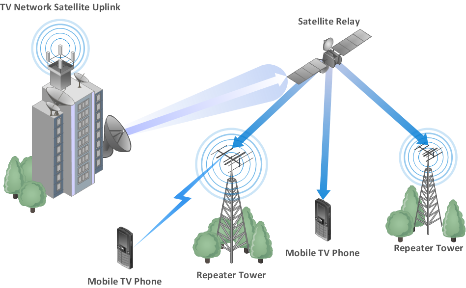
ATM Network. Computer and Network Examples


ATM Solutions
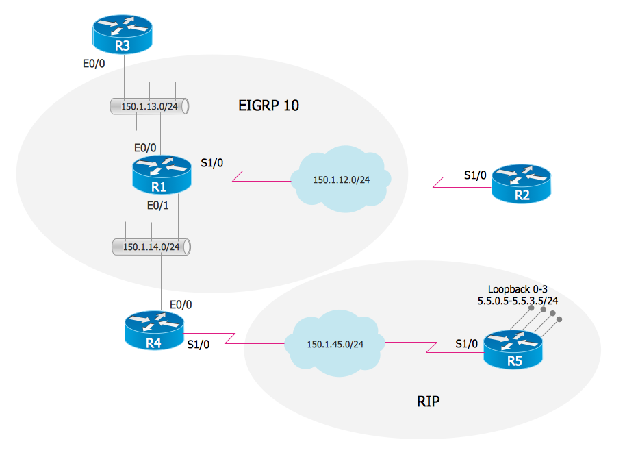
EIGRP. Computer and Network Examples
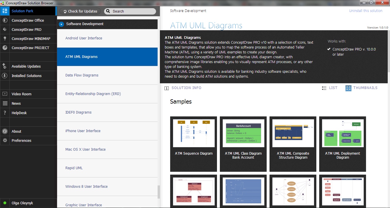
 ATM UML Diagrams
The ATM UML Diagrams solution lets you create ATM solutions and UML examples. Use ConceptDraw DIAGRAM as a UML diagram creator to visualize a banking system.
UML Deployment Diagram Example - ATM System UML diagrams

Network Glossary Definition

Building Networks
UML Use Case Diagram Example. Services UML Diagram. ATM system

Network Topologies


Yourdon and Coad Diagram

The vector stencils library "Cisco routers" contains 27 symbols of routers for drawing Cisco computer network diagrams.
"When multiple routers are used in interconnected networks, the routers exchange information about destination addresses using a dynamic routing protocol. Each router builds up a table listing the preferred routes between any two systems on the interconnected networks. A router has interfaces for different physical types of network connections, (such as copper cables, fiber optic, or wireless transmission). It also contains firmware for different networking Communications protocol standards. Each network interface uses this specialized computer software to enable data packets to be forwarded from one protocol transmission system to another.
Routers may also be used to connect two or more logical groups of computer devices known as subnets, each with a different sub-network address. The subnets addresses recorded in the router do not necessarily map directly to the physical interface connections." [Router (computing). Wikipedia]
The symbols example "Cisco routers - Vector stencils library" was created using the ConceptDraw PRO diagramming and vector drawing software extended with the Cisco Network Diagrams solution from the Computer and Networks area of ConceptDraw Solution Park.
www.conceptdraw.com/ solution-park/ computer-networks-cisco
Router

Router, subdued

Router with silicon switch

Wavelength router

NetFlow router

uBR 910

Broadband router

Gigabit switch ATM tag router

ATM tag switch router

ATM router

NetFlow router

Cisco 7505

Cisco 7507

Cisco 7500 ARS (7513)
-cisco-routers---vector-stencils-library.png--diagram-flowchart-example.png)
Voice enabled router

TDM router

IP telephony router

IAD router

Content service router

Cisco storage router

Router with firewall

Wireless router

ASR 1000 series

ATM 3800

AXP

Cable modem

Ground terminal

UML Collaboration Diagram. Design Elements

Bank UML Diagram

Swim Lane Flowchart Symbols

Digital Communications Network. Computer and Network Examples

- Atm Topology In Data Communication And Networking
- Communication network diagram | ATM Network. Computer and ...
- Data Communication Network
- Atm Protocol In Data Communications And Networking
- Near field communication (NFC). Computer and Network Examples ...
- ATM Network. Computer and Network Examples | Network ...
- Atm And Atm Topology And Atm Protocol In Data Communication
- What Is Atm Topology In Data Communication And Network
- Diagram For Data Communications In Computer Networks
- Data Communication And Network Atm Protocol
- Asynchronous Transfer Mode Topology In Data Communication And
- Atm Topology In Data Communications And Networking
- Examples Of Data Communication
- Atm Topology Types In Data Communication And Network
- Network Topologies | Atm Diagram In Dcn
- ATM Network. Computer and Network Examples | EIGRP. Computer ...
- Atm Topology In Data Communication And Networks
- ATM Network. Computer and Network Examples | Tree Network ...
- ATM Network. Computer and Network Examples | Building Networks ...
- Computer Network Diagrams | ATM Network. Computer and ...