Wiring Diagrams with ConceptDraw DIAGRAM
A Wiring Diagram is a comprehensive schematic that depicts the electrical circuit system, shows all the connectors, wiring, signal connections (buses), terminal boards between electrical or electronic components and devices of the circuit. Wiring Diagram illustrates how the components are connected electrically and identifies the wires by colour coding or wire numbers. These diagrams are necessary and obligatory for identifying and fixing faults of electrical or electronic circuits, and their elimination. For designing Wiring Diagrams are used the standardized symbols representing electrical components and devices. ConceptDraw Solution Park offers the Electrical Engineering solution from the Engineering area with 26 libraries of graphics design elements and electrical schematic symbols for easy drawing various Wiring Diagrams, Electrical Circuit and Wiring Blueprints, Electrical and Telecom schematics of any complexity, Electrical Engineering Diagrams, Power Systems Diagrams, Repair Diagrams, Maintenance Schemes, etc. in ConceptDraw DIAGRAM software.The Rack
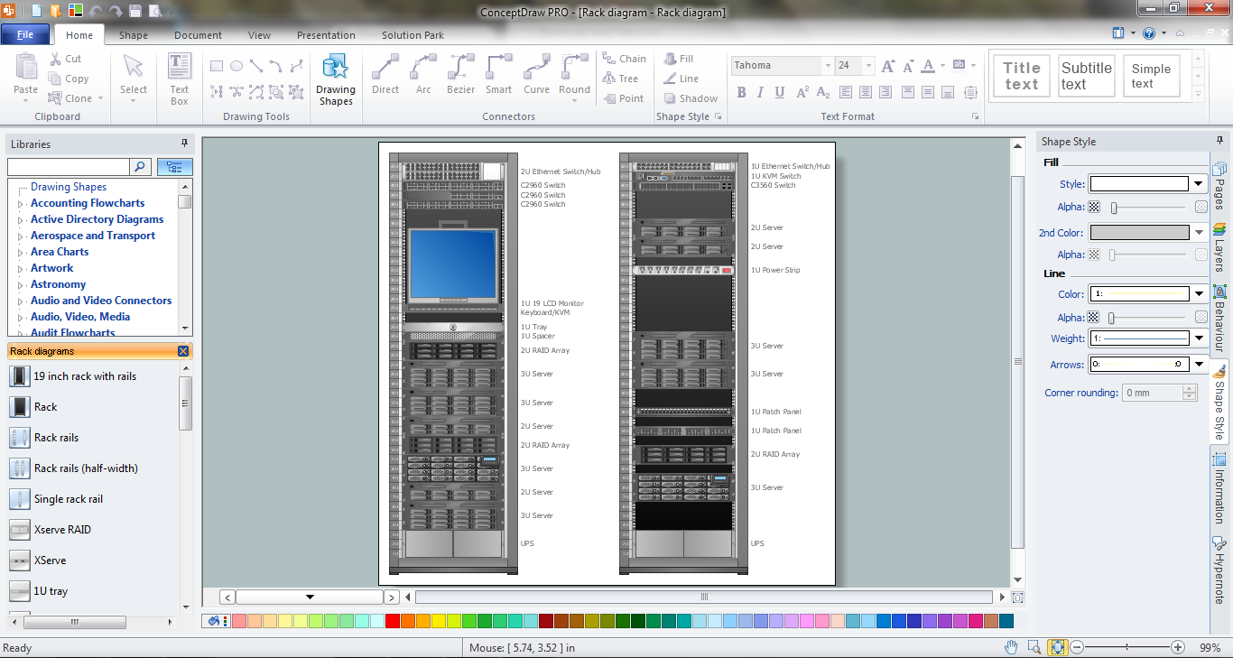
The Rack Diagrams represent the frontal view of the rack with network equipment installed. They are helpful and widely used for choosing the equipment and racks to buy, and give the possibility to visually plan how to organize it on the racks. Now creating of the Rack Diagrams is quite simple and quick thanks to the powerful drawing tools of the Rack Diagrams Solution from the Computer and Networks Area.
 Rack Diagrams
The Rack Diagrams solution, including a vector stencil library, a collection of samples and a quick-start template, can be useful for all who deal with computer networks. Choosing any of the 54 library's vector shapes, you can design various types of Rack diagrams or Server rack diagrams visualizing 19" rack mounted computers and servers.
 Computer and Networks Area
The solutions from Computer and Networks Area of ConceptDraw Solution Park collect samples, templates and vector stencils libraries for drawing computer and network diagrams, schemes and technical drawings.
 Electric and Telecom Plans
The Electric and Telecom Plans solution providing the electric and telecom-related stencils, floor plan electrical symbols and pre-made examples is useful for electricians, interior designers, telecommunications managers, builders and other technicians when creating the electric visual plans and telecom drawings, home electrical plan, residential electric plan, telecom wireless plan, electrical floor plans whether as a part of the building plans or the independent ones.
- Rack units | Rack diagram - Template | Rack units | Rack Unit
- Gym and Spa Area Plans | Safety and Security | Audio , Video, Media ...
- Audio and Video Connectors | Audiovisual system hook up diagram ...
- Rack Diagrams | How to Create a Rack Diagram in ConceptDraw ...
- Marketing Diagrams | Active Directory Diagrams | Audio and Video ...
- Network Glossary Definition | Audio and Video Connectors ...
- Audio and Video Connectors | ConceptDraw Solution Park ...
- Fishbone Diagram | Project Management Area | Rack Diagrams ...
- Video and audio - Vector stencils library | Rack Diagrams | Audio ...
- Audio Equipment Installation Diagrams
- Audio Visual Connectors Types | Standard Universal Audio & Video ...
- Rack diagram - Template | Cisco Products Additional. Cisco icons ...
- Rack diagrams - Vector stencils library | Call shop solution | Rack ...
- Audio Video Connections | S Video Connection | Video Connectors ...
- Equipment Rack
- Value Stream Mapping Icons | Learn how to create a current state ...
- Rack diagrams - Vector stencils library | Rack diagram - Template ...
- Telecommunication Network Diagrams | Rack Diagrams ...
- How To use House Electrical Plan Software | Audio , Video, Media ...

