HelpDesk
How to Convert Visio Stencils for Use in ConceptDraw DIAGRAM
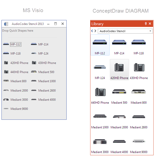
MS Visio provides users with a number of predefined stencils. Standard Visio stencils contain shapes that are basically used to create diagrams. The shapes can range from simple flow chart boxes or lines to more complicated shapes like servers, racks or anything else that needs to be represented in a graphical form. ConceptDraw DIAGRAM supports the possibility to open Visio stencils. With the introduction of Visio 2013, Microsoft has changed the native file format used in earlier versions of Microsoft Visio. Thus, when you are looking for a professional tool to open and save in the newer Visio 2013 file format on Mac, ConceptDraw DIAGRAM is the solution for you. ConceptDraw DIAGRAM file import and export work round-trip with the new Visio VSDX file format and at the same time supports the improved import of VDX file format. To use Visio stencils created with MS Visio 2010 in your diagrams, created with ConceptDraw DIAGRAM, follow the steps described in the following article.Network Layout
The Network Layout Diagram visually illustrates the arrangement of computers, nodes and other network appliances, such as servers, printers, routers, switches, hubs, and their relationships between each other. The network layout and placement of servers greatly influence on the network security and network performance. Elaboration of robust Network Layout Diagram is especially important when visualizing already existing network in order to understand its complexity; when troubleshooting the network issues; designing, documenting and implementing new network configurations; extending, modifying, or moving an existing network to other location. Through the careful thinking the network plan and designing the clear Network Layout Diagram, you can be confident in result on the stage of network implementation and to solve faster the problems appearing in network infrastructure. ConceptDraw DIAGRAM enhanced with Computer Network Diagrams solution from Computer and Networks area perfectly suits for drawing Network Layout Diagrams for different network topologies.
 Plumbing and Piping Plans
Plumbing and Piping Plans solution extends ConceptDraw DIAGRAM.2.2 software with samples, templates and libraries of pipes, plumbing, and valves design elements for developing of water and plumbing systems, and for drawing Plumbing plan, Piping plan, PVC Pipe plan, PVC Pipe furniture plan, Plumbing layout plan, Plumbing floor plan, Half pipe plans, Pipe bender plans.
- How To use House Electrical Plan Software | Socket In Autocad Icon
- How To use House Electrical Plan Software | Autocad Icon For ...
- Autocad Layout Plan Icon
- Autocad Symbol For Valve
- Fire Hydrant Symbol Autocad
- How To use House Electrical Plan Software | Electrical Symbols ...
- Layout Of Socket Connection In Autocad
- How To use House Electrical Plan Software | Cctv Symbols Autocad
- Gas Symbol Autocad
- Cctv Dome Camera Autocad Drawing
- How To Create CCTV Network Diagram | CCTV Network Example ...
- Drawing Autocad Dwg Block Wireless Router
- Autocad Network Diagram
- Cisco Routers. Cisco icons , shapes, stencils and symbols | Design ...
- Cctv Icon Dwg
- Lighting and switch layout | How To use House Electrical Plan ...
- How To use House Electrical Plan Software | Fire Exit Plan. Building ...
- Camera layout schematic | CCTV Network Example | Camera layout ...
- Building Drawing Software for Design Seating Plan | Interior Design ...
- Restaurant Floor Plan Autocad

