Basic Flowchart Symbols and Meaning
Flowcharts are the best for visually representation the business processes and the flow of a custom-order process through various departments within an organization. ConceptDraw PRO diagramming and vector drawing software extended with Flowcharts solution offers the full set of predesigned basic flowchart symbols which are gathered at two libraries: Flowchart and Flowcharts Rapid Draw. Among them are: process, terminator, decision, data, document, display, manual loop, and many other specific symbols. The meaning for each symbol offered by ConceptDraw gives the presentation about their proposed use in professional Flowcharts for business and technical processes, software algorithms, well-developed structures of web sites, Workflow diagrams, Process flow diagram and correlation in developing on-line instructional projects or business process system. Use of ready flow chart symbols in diagrams is incredibly useful - you need simply drag desired from the libraries to your document and arrange them in required order. There are a few serious alternatives to Visio for Mac, one of them is ConceptDraw PRO. It is one of the main contender with the most similar features and capabilities.
Sample Project Flowchart. Flowchart Examples
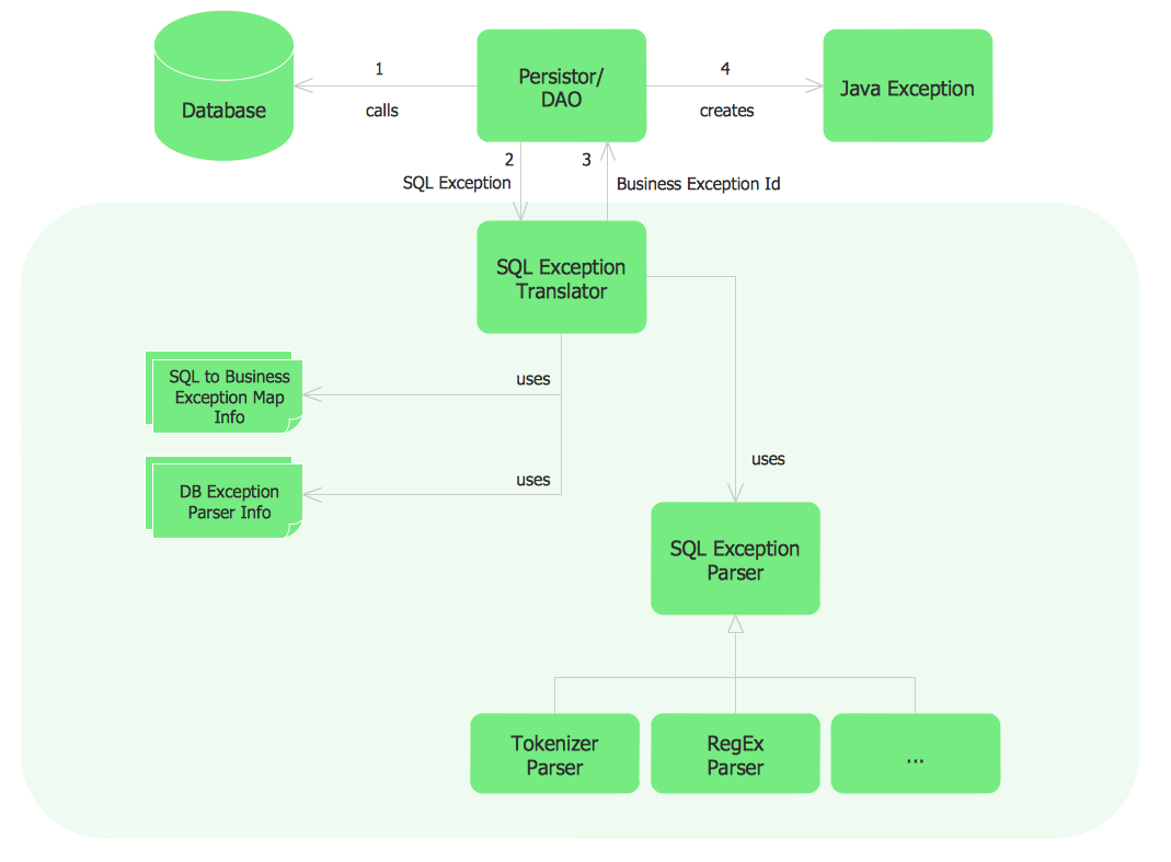
This sample shows the Flowchart that displays the architecture of SQL Exception Translation. This sample was created in ConceptDraw PRO diagramming and vector drawing software using the Flowcharts solution from the Diagrams area of ConceptDraw Solution Park.
UML Deployment Diagram. Design Elements
UML Deployment diagram describes the hardware used in system implementations and the execution environments and artifacts deployed on the hardware. ConceptDraw has 393 vector stencils in the 13 libraries that helps you to start using software for designing your own UML Diagrams. You can use the appropriate stencils of UML notation from UML Deployment library.IDEF4 Standard
Use Case Diagrams technology. IDEF4 standard implies not only graphical presentation but the additional information about diagrams of heredity, methods systematization and types which are contained in specifications.Booch OOD Diagram
The vector stencils library Booch OOD from the solution Software Engineering contains specific symbols of the Booch method such as class symbols, association symbols, aggregation symbols for ConceptDraw PRO diagramming and vector drawing software. The Software Engineering solution is contained in the Software Development area of ConceptDraw Solution Park.Yourdon and Coad Diagram
The vector stencils library Yourdon and Coad Notation from the solution OOAD contains specific symbols of the Yourdon and Coad notation such as data store symbol, data process symbol, loop symbol for ConceptDraw PRO diagramming and vector drawing software. The OOAD solution is contained in the Software Development area of ConceptDraw Solution Park.- Basic Flowchart Symbols and Meaning | Sample Project Flowchart ...
- Basic Flowchart Symbols and Meaning | The Building Blocks Used ...
- The Building Blocks Used in EPC Diagrams | Types of Flowcharts ...
- Basic Flowchart Symbols and Meaning | Types of Flowcharts | UML ...
- Basic Flowchart Symbols and Meaning | Block Diagram | Process ...
- Dfd Is For Oops
- Building Blocks Of A Flowchart
- Block Diagram Of Oops
- Basic Building Block Of Erd
- Building Drawing Design Element: Seat Blocks | UML Block ...
- Entity Relationship Diagram Symbols | Basic Flowchart Symbols and ...
- Flow Chart Model Building
- UML Block Diagram | About UML | The Building Blocks Used in EPC ...
- Database Design | Booch OOD Diagram | UML Flowchart Symbols ...
- Process Flowchart | How to Create a Bank ATM Use Case Diagram ...
- Sample Project Flowchart . Flowchart Examples | Flowchart ...
- UML Block Diagram | UML Class Diagram Notation | Functional ...
- New Cooking Recipes Solution for ConceptDraw PRO
- Sequence Diagram Tool | Order processing center - UML sequence ...


