The vector stencils library "Qualifying" contains 56 qualifying symbols of radiation, polarity, phase, windings, wire, ground, connection, connector, coaxial, electret.
Use these signs to annotate or specify characteristics of objects in electrical drawings, electronic schematics, circuit diagrams, electromechanical drawings, and wiring diagrams, cabling layout diagrams.
"An electrical drawing, is a type of technical drawing that shows information about power, lighting, and communication for an engineering or architectural project. Any electrical working drawing consists of "lines, symbols, dimensions, and notations to accurately convey an engineering's design to the workers, who install the electrical system on the job".
A complete set of working drawings for the average electrical system in large projects usually consists of:
(1) A plot plan showing the building's location and outside electrical wiring.
(2) Floor plans showing the location of electrical systems on every floor.
(3) Power-riser diagrams showing panel boards.
(4) Control wiring diagrams.
(5) Schedules and other information in combination with construction drawings.
Electrical drafters prepare wiring and layout diagrams used by workers who erect, install, and repair electrical equipment and wiring in communication centers, power plants, electrical distribution systems, and buildings." [Electrical drawing. Wikipedia]
The signs example "Design elements - Qualifying" was drawn using the ConceptDraw PRO diagramming and vector drawing software extended with the Electrical Engineering solution from the Engineering area of ConceptDraw Solution Park.
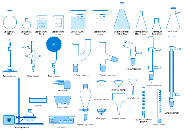
The vector stencils library "Laboratory equipment" contains 31 clipart icons of chemical laboratory equipment and labware for drawing part assembly and mounting schemes of glassware apparatus in chemical experiment diagrams and illustrations.
"Laboratory glassware refers to a variety of equipment, traditionally made of glass, used for scientific experiments and other work in science, especially in chemistry and biology laboratories. ...
Glass use in laboratory applications is not as commonplace as it once was because of cheaper, less breakable, plasticware; however, certain applications still require glassware because glass is relatively inert, transparent, heat-resistant, and easy to customize. The type of glass used is dependent on the application. Borosilicate glass, which is commonly used in reagent bottles, can withstand thermal stress. Quartz glass, which is common in cuvettes, can withstand high temperatures and is transparent in certain parts of the electromagnetic spectrum. Darkened brown or amber (actinic) glass, which is common in dark storage bottles, can block ultraviolet and infrared radiation. Heavy-wall glass, which is common in glass pressure reactors, can withstand pressurized applications." [Laboratory glassware. Wikipedia]
The chemical symbols example "Design elements - Laboratory equipment" was created using the ConceptDraw PRO software extended with the Chemistry solution from the Science and Education area of ConceptDraw Solution Park.
The vector stencils libraries "Pipes 1" and "Pipes 2" contain 28 and 48 pipe, tubing and fitting symbols, respectively.
"Pipe is hollow cylinder used to conduct or transfer fluids (liquids and gases) from one place to other place. The main difference between pipe and tube is the critical dimension used to describe the pipe size or the tube size. For pipe, internal diameter (ID) roughly corresponds to the nominal pipe size for standard wall thickness. For tube, the outer diameter (OD) closely corresponds to the tube size. In current European standards pipes and tubes are nowadays described as outside diameter by wall thickness. The three standard types of pipe ends used in the piping industriesare; Plain Ends (PE), Threaded Ends (TE) and Beveled Ends (BE). In the past, many types of material have been used in conveying water from one point to another. Masonry and wood were probably the first materials used. Plastics are the newest, and are now being used quite extensively." [Piping. Wikipedia]
Use the design elements libraries "Pipes 1" and "Pipes 2" for drawing plumbing and piping building plans, schematic diagrams, blueprints, or technical drawings of waste water disposal systems, hot and cold water supply systems using the ConceptDraw PRO diagramming and vector drawing software.
The shapes libraries "Pipes 1" and "Pipes 2" are contained in the Plumbing and Piping Plans solution from the Building Plans area of ConceptDraw Solution Park.
The vector stencils library "Telecom" contains 20 telecommunication icons. Use it to design your IT and telecom illustrations and infographics with ConceptDraw PRO diagramming and vector drawing software.
"Telecommunication is the transmission of signs, signals, writings, images and sounds or intelligence of any nature by wire, radio, optical or other electromagnetic systems, as defined by the International Telecommunication Union (ITU).
Telecommunication occurs when the exchange of information between communication participants includes the use of technology. It is transmitted either electrically over physical media, such as cables, or via electromagnetic radiation. Such transmission paths are often divided into communication channels which afford the advantages of multiplexing. ...
Modern technologies for long-distance communication usually involve electrical and electromagnetic technologies, such as telegraph, telephone, and teleprinter, networks, radio, microwave transmission, fiber optics, and communications satellites." [Telecommunication. Wikipedia]
The telecommunication icon set example "Design elements - Telecom" is included in the Computers and Communications solution from the Illustration area of ConceptDraw Solution Park.
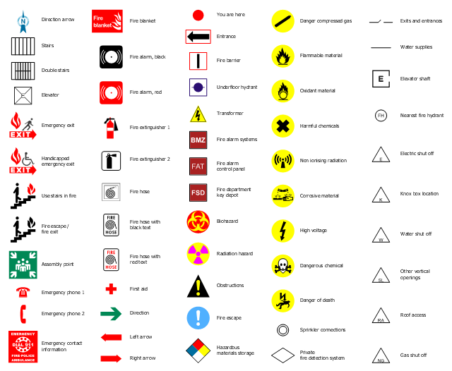
The design elements library "Fire and emergency planning" contains 52 fire safety symbols for developing the fire escape plans using the ConceptDraw PRO diagramming and vector drawing software.
The fire escape plan shows the location of fire alarm and extinguishing equipment, stairs and emergency exits, and evacuation orders and path.
"Hazard symbols are recognizable symbols designed to warn about hazardous materials, locations, or objects, including electric currents, poisons, and other things. The use of hazard symbols is often regulated by law and directed by standards organizations. Hazard symbols may appear with different colors, backgrounds, borders and supplemental information in order to specify the type of hazard." [Hazard symbol. Wikipedia]
The vector stencils library Fire and emergency planning is included in the Fire and Emergency Plans solution from the Building Plans" area of ConceptDraw Solution Park.
www.conceptdraw.com/ solution-park/ building-fire-emergency-plans
- Piping Drawing Basics
- Design elements - Qualifying | ERD Symbols and Meanings | Basic ...
- Mechanical Design Software | Star Network Topology | Physics ...
- Basic Flowchart Symbols and Meaning | ERD Symbols and ...
- Design elements - Qualifying | ERD Symbols and Meanings | Basic ...
- Basic Flowchart Symbols and Meaning | Design elements ...
- ERD Symbols and Meanings | Design elements - Qualifying | Basic ...
- Design elements - Qualifying | Electrical Symbols, Electrical ...
- Process Flowchart | Design elements - Qualifying | Cafe electrical ...
- Mechanical Drawing Symbols | Design elements - Dimensioning ...
- Signs And Symbols For Building Plan Drawings
- Electrical Drawing Software and Electrical Symbols | Design ...
- Design elements - Qualifying | Technical Drawing Software | Local ...
- Electrical Symbols, Electrical Diagram Symbols | Electrical Drawing ...
- Design elements - Qualifying | Cafe electrical floor plan | How To ...
- Design elements - Qualifying | Electrical Drawing Software and ...
- Mechanical Drawing Symbols | Mechanical Engineering | Design ...
- Mechanical Drawing Symbols | Design elements - Bearings | Create ...
- Process Flowchart | Mechanical Drawing Symbols | Basic Flowchart ...


.png--diagram-flowchart-example.png)
